
3D Layout
The 3D Layout tool supports viewing and re-editing indoor scenes that had Smart Space Recognition enabled during model reconstruction.
Note:
- 3D Layout is only available for indoor scenes that had Smart Space Recognition enabled during reconstruction
- A 3D Layout license is required to use this feature
Opening & Activating
V2.2 Upgrade: Auto-Import — When importing LCC, the system automatically detects and associates the corresponding floor plan data. A floor plan child node appears automatically under the LCC node in the asset panel and activates on selection. No manual import needed.
- If no floor plan data exists, LCC loads normally without error
- If auto-association fails, a toast message appears: "Floor plan auto-association failed. You can bind it manually."
Manual Import (entry retained):
- File → Import → Floor plan file directory → Select the
semantic-resultfolder in the project directory - Click Confirm
- In Scene Mode, click 3D Layout in the toolbar to enter the interface
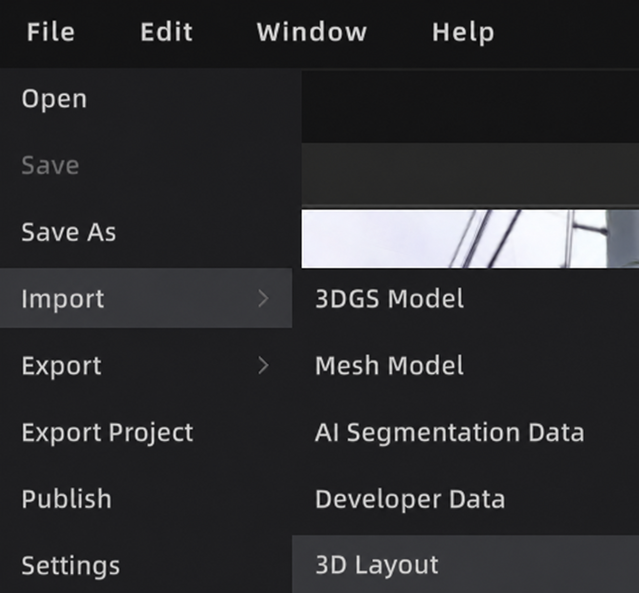
Import Floor Plan File
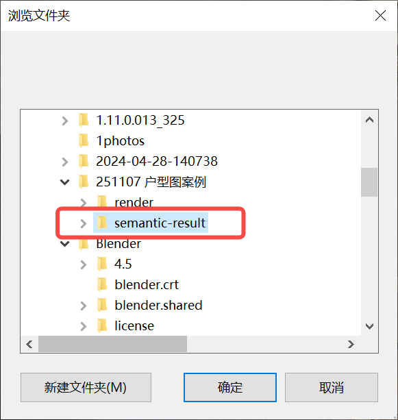
Select Floor Plan Directory
Interface & Tools
- The 3D Layout canvas supports zooming in and out, dragging, and panning
- The canvas supports 2D, 3D, and split-screen views, as well as a 2D overlay
- In V2.4, the Asset Management Panel is located on the right side of the 3D Layout workspace and remains there when you switch between 2D, 3D, and split-screen views
- The information hierarchy, asset groups, selection states, expand or collapse behavior, and right-click operations in the Asset Management Panel remain unchanged
- After you exit 3D Layout, other feature panels retain their original layout
Drawing Tools
Wall
Click Wall → place start point → adjust position → place end point → right-click to finish.
- Single-line and double-line walls use the same drawing and editing operations
- Wall intersections remain continuous, with no openings, gaps, or incorrect truncation at the intersection
- If the drawing length is zero or no valid wall segment is formed, no wall is created
- Canceling a drawing leaves no unfinished wall or preview artifact
Single-Line and Double-Line Wall Display
Use the wall display button in the upper-right corner of the 3D Layout interface to switch between the two 2D wall display modes. The button indicates which mode is currently active.
| Display Mode | 2D Appearance |
|---|---|
| Single-Line Wall | The wall is displayed in gray |
| Double-Line Wall | The wall is displayed as transparent |
The selected mode applies to both existing walls and walls drawn afterward. Switching modes changes only the wall appearance in the 2D view and exported assets; it does not modify wall data, geometry positions, or 3D wall results.
Door
Click Door → place pivot point → adjust width → confirm end point → adjust orientation.
Window
Click Window → place start point → adjust width → confirm end point.
Doors and windows snap to walls. Their openings interrupt the wall display only within the corresponding span; they do not delete or split the underlying wall data. After a wall, door, or window is moved or edited, the door or window remains constrained to the wall and the opening display updates accordingly. This behavior applies to both new and existing 3D Layouts.
Text Annotation
Click T → place text box → double-click to activate → type text → click empty area to finish.
Polygon Drawing
Click Polygon → single-click to add control points → double-click to finish.
Rectangle Drawing
Click Rectangle → drag to draw → release to finish.
Quick View Adjustment
Provides quick-align and 90° rotation shortcuts for fast canvas orientation adjustments in 2D view.
Export 3D Layout
3D Layout supports exporting JPEG images, OBJ 3D models, and DXF files. Existing JPEG and OBJ formats and export rules remain unchanged. Exported assets use the single-line or double-line wall display mode selected at the time of export. Hidden assets are not exported.
Export JPEG or OBJ
In the Asset Management Panel, right-click the 3D Layout, select Export JPEG or Export OBJ, and then choose a save location as prompted.
Export DXF
- In the Asset Management Panel on the right, select the 3D Layout asset you want to export
- Right-click the selected 3D Layout and select Export DXF
- In the DXF export settings, select Exterior Wall Dimensions and Interior Wall Dimensions as needed
- Start the export and choose a local save location
- Wait for the export to finish; the file is saved with the
.dxfextension
The Export DXF option is not displayed unless a 3D Layout asset is selected.
Exterior Wall Dimensions and Interior Wall Dimensions are independent options and support all four combinations:
| Exterior Wall Dimensions | Interior Wall Dimensions | Export Result |
|---|---|---|
| Selected | Not Selected | Wall geometry and exterior wall dimensions; interior wall dimensions are excluded |
| Not Selected | Selected | Wall geometry and interior wall dimensions; exterior wall dimensions are excluded |
| Selected | Selected | Wall geometry, exterior wall dimensions, and interior wall dimensions |
| Not Selected | Not Selected | Wall geometry only, with no dimension annotations |
Leaving a dimension option unselected excludes only that type of dimension annotation; it does not affect the corresponding wall geometry. After a successful export, the interface provides success feedback. If the export fails, the interface displays the reason or a clear error message and does not generate an unusable file.
Asset Management
After importing floor plan data, recognized components (walls, doors, windows, etc.) are automatically grouped by type in the Asset Management Panel.
Asset group operations (right-click):
- Delete
- Export OBJ
- Export JPEG
- Export DXF (when a 3D Layout asset is selected)
Single asset operations (right-click):
- Clone
- Delete
- Rename
Shortcuts:
Shift+ click: Add to selectionCtrl+ click: Remove from selection- Select and press
Delete: Delete selected assets