
Frame Rate Tuning for 3DGS Scenes in UE5
Step One: Locate the Bottleneck
Before changing any parameter, confirm that the frame rate drop is caused by 3DGS. Lighting, shadows, post-processing, regular models, and Blueprint logic in the scene can all be the real bottleneck, in which case no amount of LCC parameter tuning helps.
Confirm the Bottleneck Comes From 3DGS
Hide or remove everything in the scene other than 3DGS and compare the frame rate:
- Record the current frame rate as the baseline (
stat fpsorstat unit). - Hide the LCC Actor, keep the rest of the scene, and record the frame rate.
- Do the opposite: keep only the LCC Actor, hide or remove the other models, lights, post-process volumes, and UI, and record the frame rate.
When the original scene has many elements and hiding them one by one is impractical, a cleaner approach is to create an empty level with a single LCC Actor loading the same data, then record the frame rate from the same viewpoint. That removes all interference from the original scene and gives the performance baseline of 3DGS itself.
Compare the three sets of numbers:
| Result | Conclusion |
|---|---|
| Frame rate is still low with only LCC | The bottleneck is 3DGS, so continue with the following steps |
| Frame rate does not recover noticeably after hiding LCC | The bottleneck is elsewhere in the scene, so optimize that part first |
| Both are fine alone and only low together | The total exceeds the hardware budget, so reduce both sides or lower the resolution |
Rule Out the Default Scene Elements of the Engine
A new level ships with a set of default Actors, and several of them are not cheap, so they are easily mistaken for 3DGS cost. The most typical is VolumetricCloud: it performs volumetric ray marching every frame and keeps consuming GPU even when only a small patch of sky is visible.
When the project does not need sky effects, delete the following Actors from the level:
| Actor | Description |
|---|---|
| VolumetricCloud | Volumetric clouds, significant GPU cost, usually unnecessary in a pure 3DGS scene |
| ExponentialHeightFog | Height fog, which also affects the look when layered over 3DGS |
| SkyAtmosphere | Atmospheric scattering, keep only when the sky is needed |
3DGS data usually already contains environment information, so these effects are unnecessary in most cases. Measure the frame rate again after deleting them, then judge whether LCC parameters still need tuning.
Keep test conditions fixed, otherwise the numbers cannot be compared: the same map and spawn point, the same camera position or path, the same resolution and Screen Percentage, and the same on/off state for Lumen, virtual shadow maps, post-processing, and SceneCapture. Run a warm-up pass before recording so the first shader compilation and the first disk read do not mix into the stable frame rate. Change one category of settings at a time.
Common observation commands:
stat fps         // Frame rate
stat unit        // The four frame times: Frame / Game / Draw / GPU
stat gpu         // GPU Pass breakdown
stat rhi         // Draw calls, primitives, video memory
ProfileGPU       // Per-frame GPU Pass detail
Use the LCC Statistics Once 3DGS Is Confirmed
Open the statistics panel with Actions > Stats in the Actor panel, or enter stat xgrids in the console.
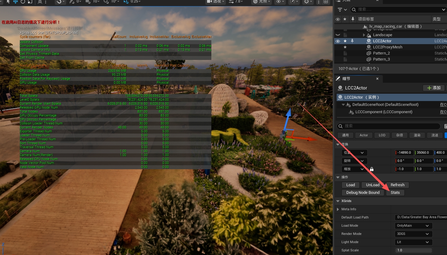
Viewing the LCC real-time performance statistics with stat xgrids
For parameter details, see Performance Parameters: Statistics
Focus on Current Render Main Splats and Current Render Nodes: the direct cause of most performance problems is too many points rendered on screen at once.
Turn On LOD Visualization at the Same Time
While reading the statistics, use Actions > Debug Node Bound in the Actor panel to visualize node Levels and confirm the LOD distribution of the current view directly. Warmer colors mean a lower Level and higher detail.
The idea of optimization is to reduce on-screen points as far as the look allows, with a focus on how far Level 0 extends:
- How far do the warm-colored areas in the image reach? Is the highest-precision data really needed at that distance?
- If the switch to coarser Levels happens earlier, is the drop in the look perceptible?
In most scenes Level 0 reaches farther than actually needed, and making it switch to coarser Levels earlier lowers the point count immediately, which is the most effective of all the options. Once headroom is confirmed, move on to Step Two and tune Level Factor.
Step Two: Adjust LOD
This is the step with the most obvious benefit. In most scenes Level 0 reaches far beyond what is actually needed, and making it switch to coarser Levels earlier drops the on-screen point count immediately, usually with no perceptible change in the look. Do this step first, then consider the later options.
LOD has three independent knobs (Level Factor, Start Level, End Level)
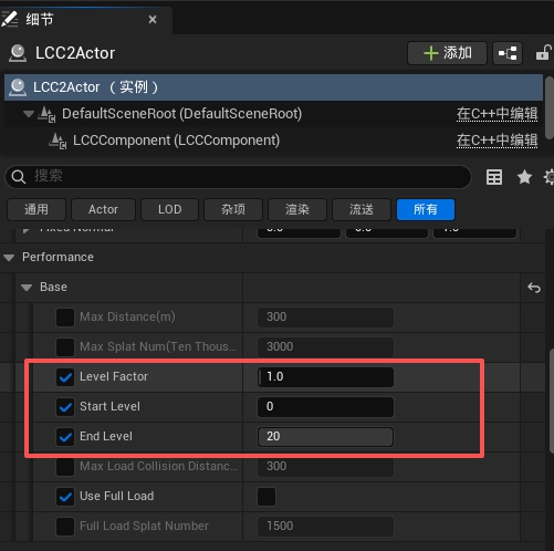
Configuring Level Factor, Start Level, and End Level
2.1 First Determine How Level Factor Works
The two pipelines select Levels through different mechanisms, so Level Factor works differently as well, but the direction is the same: the larger the value, the earlier nodes switch to lower-detail Levels.
| Pipeline | Basis of Level selection | What Level Factor does |
|---|---|---|
| LCC | The global RangeForLevel distance table | Divides the whole distance table by this value |
| LCC2 | Screen-space error (SSE) | Divides the computed SSE by this value, and refinement stops once the error is small enough |
LCC2 Pipeline: Screen-space Error
LCC2 does not use RangeForLevel; it computes a screen-space error for every node instead: how many pixels the geometric error of the node itself covers when projected to the screen. When the error exceeds the threshold, it refines to finer child nodes, otherwise it stays at the current Level.
This error is affected by node distance, view angle, and screen resolution at the same time, so the same Level Factor does not produce the same actual switch distance at different resolutions or FOVs. That also means the LOD distribution of LCC2 cannot be calculated in advance from a distance table and can only be observed in practice with the Debug Node Bound in 2.5.
Tuning works the same way as the LCC pipeline, so go straight to the test ladder in 2.2.
LCC Pipeline: Distance Table
Level Factor divides the global RangeForLevel array by its value. The larger the value, the shorter the effective distance of each Level and the earlier nodes enter a lower-detail Level.
RangeForLevel defaults (11 items, ProjectSettings > Plugins > LCC4Unreal > Level):
Level:  0    1    2    3    4    5    6    7    8    9    10
meters: 15   50   80  110  140  170  190  220  250  280   350
Effective distances after dividing by Level Factor (in meters, non-integers shown rounded):
| Level Factor | 0 | 1 | 2 | 3 | 4 | 5 | 6 | 7 | 8 | 9 | 10 |
|---|---|---|---|---|---|---|---|---|---|---|---|
| 1.0 (default) | 15 | 50 | 80 | 110 | 140 | 170 | 190 | 220 | 250 | 280 | 350 |
| 1.25 | 12 | 40 | 64 | 88 | 112 | 136 | 152 | 176 | 200 | 224 | 280 |
| 1.5 | 10 | 33 | 53 | 73 | 93 | 113 | 127 | 147 | 167 | 187 | 233 |
| 2.0 | 7.5 | 25 | 40 | 55 | 70 | 85 | 95 | 110 | 125 | 140 | 175 |
How to read this table: at Level Factor = 2, the highest detail used to apply within 15 meters and now applies only within 7.5 meters. That is far more precise than saying "half the detail": what changes is the effective distance of each Level, not the point ratio.
The exact way Levels are compared against distances (upper or lower bound, open or closed interval) is an internal implementation detail. The table above is for estimating how much to adjust; confirm the actual Level distribution with the Debug Node Bound in 2.5. This table applies to the LCC pipeline only.
Beyond the last item of RangeForLevel, a node simply uses the coarsest Level available to it, so there is never a case of no Level being found. Raising Max Distance past 350 meters therefore does not require adjusting this table.
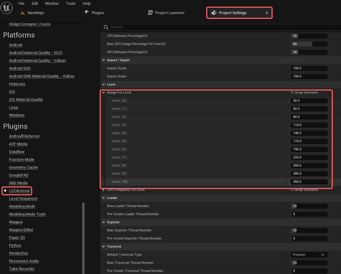
Configuring the Range For Level distance array in the project settings
2.2 Level Factor
For the range and default, see Performance Parameters: Level Factor
This is the preferred LOD knob, because it is gradual and does not cut away an entire detail Level at once.
Test ladder:
1.0 → 1.25 → 1.5 → 2.0
Check first: outlines, thin lines, small objects, ground detail, and Level transition areas. These places expose insufficient detail and LOD popping first.
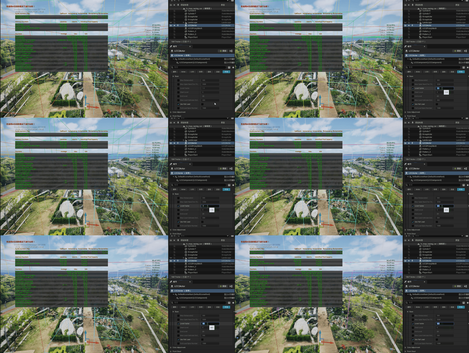
LOD changes after adjusting Level Factor
2.3 Start Level
For the range and default, see Performance Parameters: Start Level
Raising it skips the lowest-numbered (finest) Levels outright:
0 → 1 → 2
This is far more aggressive than a small Level Factor change: it discards whole Levels rather than scaling distances. Use it only when both conditions hold: stat xgrids shows Level0 Splats really is the main cost, and coarser near-field quality is acceptable. Go back to 0 when the near field is visibly blurry.
Skipping high-detail Levels after raising Start Level
2.4 End Level (normally left alone)
For the range and default, see Performance Parameters: End Level
Lowering it limits the coarsest Level that can be used: coarser Levels in the data are never used, distant content can only stay at End Level, and more points are rendered than needed. It is not a speed-up button, so keep the default unless the Level structure of the data is already understood.
Start Level <= End Level must hold; the setter does not validate it.
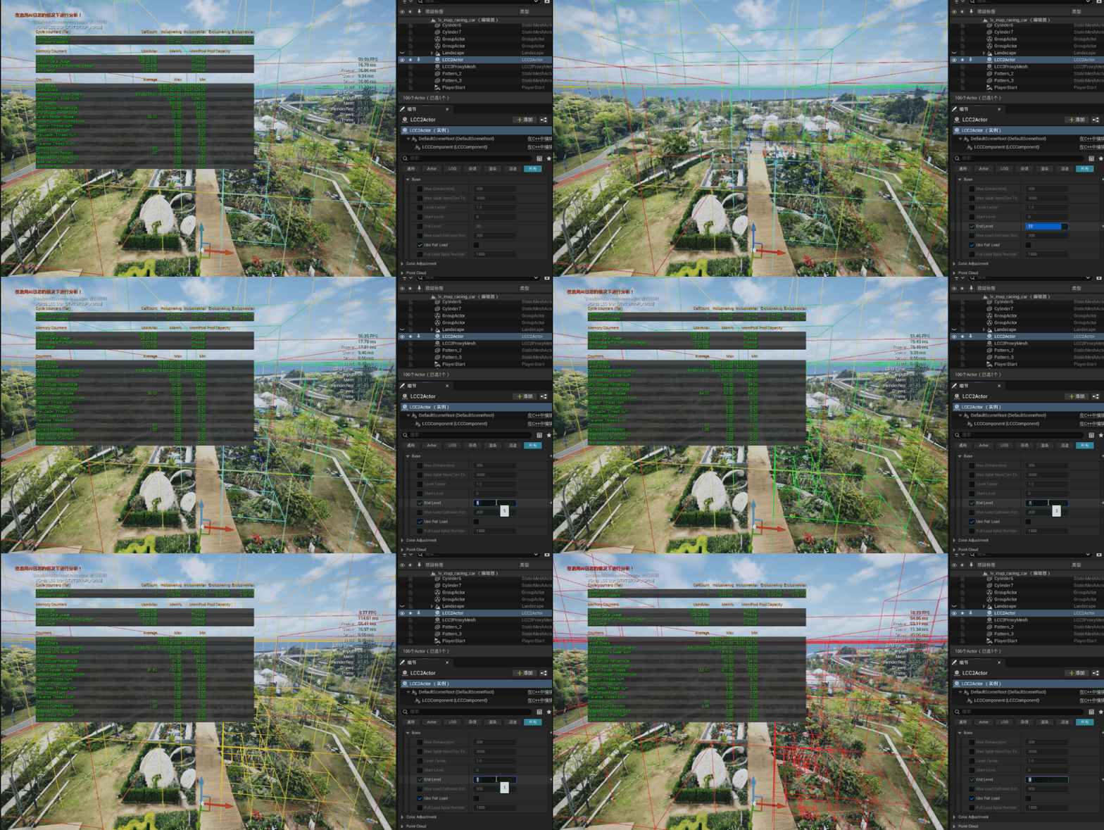
Limiting low-detail Levels after adjusting End Level
2.5 Verify With Debug Node Bound
Actions > Debug Node Bound in the Actor panel visualizes node bounds and Levels. The color sequence is red, orange, yellow, green, blue, purple, where red is the lowest Level (highest detail) and white represents the highest Level (lowest detail).
Use it to check after changing LOD parameters: whether the near field is still red/orange (high detail), whether the distance transitions smoothly into cool colors, and whether any area keeps flipping Levels at the same distance.
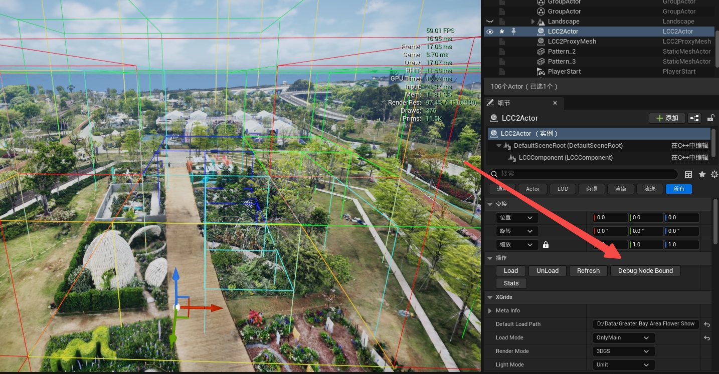
Checking the LOD distribution with Debug Node Bound
LOD Verification Points
- Whether the node count and splat count drop;
- Whether the near field becomes coarse too early;
- Whether obvious LOD popping appears while the camera moves;
Step Three: Maximum Render Distance
For the range and default, see Performance Parameters: Max Distance(m)
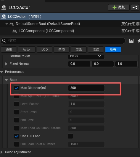
Setting the Max Distance maximum render distance
How It Differs From LOD
Max Distance cuts away data beyond the distance outright and reduces the renderable spatial range; LOD lowers precision within the range. The two are complementary: use it to tighten the range further when pressure remains after LOD tuning.
It may reduce candidate nodes along with the traversal, load, upload, sorting, and fill work that follows, but how much it reduces is implementation- and data-dependent, so verify against real statistics rather than assuming a fixed ratio of gain.
Tick the Inline Checkbox First, Otherwise Changes Do Nothing
Every parameter under the Performance category has a checkbox on its left. While the box is unchecked, the value in the text field has no effect, and the built-in default of the plugin is used at runtime. Check here first when an adjustment does nothing.
Steps for Tuning the Distance
- Stand at the position in the scene where the model data must be visible the farthest away, and measure the distance actually needed.
- Tick the checkbox to the left of the parameter.
- Set it to "the actual maximum visible distance + the necessary headroom".
- Tighten it step by step; do not drop straight to a very low value:
300 m (default) → 225 m → 150 m → fine-tune to the actual project distance
The above is a test ladder, not a recommended value. Reasonable values differ widely between interiors, city blocks, large scenes, and aerial views, so measure per project.
Render range changes after adjusting Max Distance
Distance Verification Points
- Whether
Current Render NodesandCurrent Render Splatsdrop; - Whether GPU ms or Traversal Time drops;
- Whether content disappears abruptly when walking to the distance boundary;
- Whether unloaded areas become easier to see while moving fast;
Step Four: Set a Hard Point Limit
For the range and default, see Performance Parameters: Max Splat Num
Max Distance controls the spatial range, but data density within the same range can vary enormously. Max Splat Num provides a per-frame workload cap that prevents the point count from spiking when entering a high-density area. It complements LOD and distance and cannot replace either.
Note that values that are too large are automatically clamped to the amount the GPU can render in one frame; pulling the panel value to the limit does not exceed hardware capability and merely renders the cap ineffective. To make it actually work, set it below the real point count of the current view.
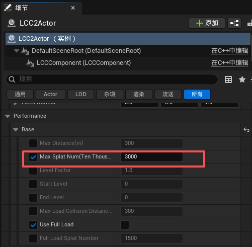
Setting the Max Splat Num per-frame point limit
Steps for Tuning the Point Limit
- Tick the checkbox to the left of the parameter.
- Lower it proportionally from the default, in units of 10,000:
3000 → 2250 → 1500 → 1000
- After each reduction, observe in a high-density area, not only in open areas.
Point count and image changes after adjusting Max Splat Num
Point Limit Verification Points
- Whether GPU ms and
Current Render Splatsdrop along with the limit; - Whether local thinning, flickering, or broken transparent structures appear.
If neither the point count nor GPU ms changes after lowering the limit, the current view never reaches that limit and this is not the current bottleneck, so go back to step one and locate it again.
Step Five: Reduce the Pixel Fill Cost
5.1 SplatScale
For parameter details, see Visual Settings: SplatScale
Reducing it lowers the screen area a single splat covers and thereby reduces transparent overlap.
Method: lower it in small steps from the current quality value, and check at high resolution, in the near field, and along object outlines. Lowering it too far makes surfaces show holes or look noticeably thin.
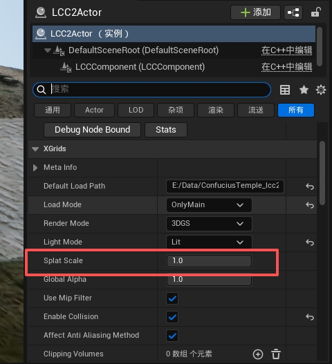
Adjusting SplatScale to reduce the screen area covered by Gaussian points
5.2 Small Splat Threshold (px) (LCC2 pipeline only)
For the range and default, see Performance Parameters: Small Splat Threshold (px)
Test it live with a CVar, no restart required:
r.LCC2.SmallSplatThreshold 0
r.LCC2.SmallSplatThreshold 0.5
r.LCC2.SmallSplatThreshold 1
The higher the value, the greater the potential gain and the more obvious the graininess in the distance. Raise it further only when GPU or SH calculation really is the bottleneck; when the data itself has no SH, the gain from skipping SH is limited.
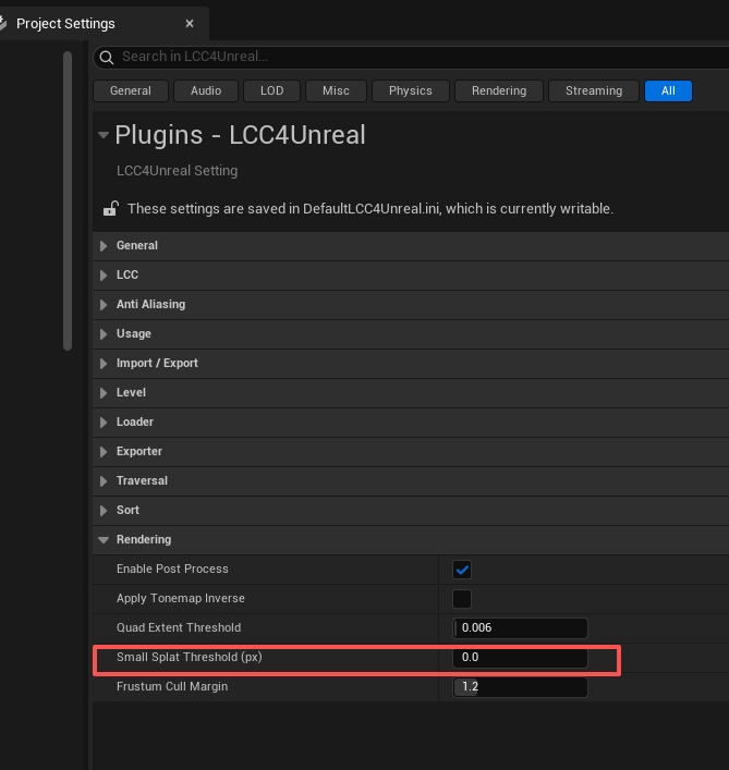
Setting the Small Splat Threshold pixel threshold
5.3 Quad Extent Threshold (LCC2 pipeline only)
For the range and default, see Performance Parameters: Quad Extent Threshold
Raising this value produces tighter quads and reduces overdraw, but it may cut semi-transparent edges.
r.LCC2.QuadExtentThreshold 0.006 → 0.008 → 0.01
Revert when outlines harden, edges go missing, or splat shapes look wrong.
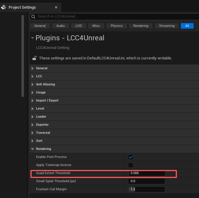
Setting Quad Extent Threshold to control the splat quad extent
5.4 Frustum Cull Margin (LCC2 pipeline only)
For the range and default, see Performance Parameters: Frustum Cull Margin
It controls the culling margin, not the point limit.
Only try lowering it toward 1.0 in small steps while no popping appears at the screen edge:
r.LCC2.FrustumMargin 1.2 → 1.1 → 1.0
Content flickering in and out at the edge while turning the camera quickly means it went too low.
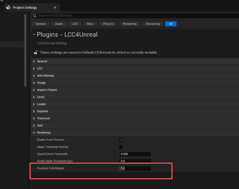
Setting the Frustum Cull Margin frustum culling margin
5.5 Anti-aliasing
The GPU cost of anti-aliasing is not low, and TSR is especially noticeable. When the scene contains only 3DGS with no regular meshes or UI, setting the matching option to None usually loses very little image quality while the frame rate gain is substantial.
For the default method of each pipeline and the trade-offs, see Performance Parameters: Anti-aliasing Methods.
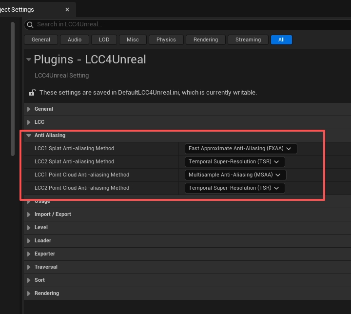
Configuring the anti-aliasing method of each LCC pipeline
Step Six: Turn Off Features That Are Not Needed
The gains in this step are clear but each comes with a functional cost, so confirm item by item that the project really does not need it rather than turning everything off.
| Feature | Pipeline | When it can be turned off | Side effect |
|---|---|---|---|
ReceiveShadows | LCC only | Shadow receiving is not needed | Loses shadow receiving |
LightMode = Lit | Common | The colors of the data already look right, or scene lights are not needed | Scene lights no longer affect LCC |
UseShcoef | Common | Only base color is needed and the look is acceptable | Loses view-dependent color variation |
SingleLayerWater Support | LCC2 only | Single layer water is not used | 3DGS cannot take part in water occlusion and refraction correctly |
EnableCollision | Common | The scene needs no collision | No collision, and navigation areas cannot be generated |
For detailed descriptions of each feature, see Visual Settings and Performance Parameters.
Step Seven: Sorting and Video Memory
Translucency sorting and video memory management are handled per pipeline: Sort Factor and extra preloading exist on LCC1 only, and the GPU video memory budget exists on LCC2 only.
7.1 Sort Factor (LCC pipeline only)
For the range and default, see Performance Parameters: Sort Factor
It applies to the global SortFrequencyForLevel table and controls how often the nodes of each Level are re-sorted. The larger the value, the fewer sorts and the better the performance, but the transparent order updates more slowly after the camera or the nodes change, which can cause brief interpenetration errors.
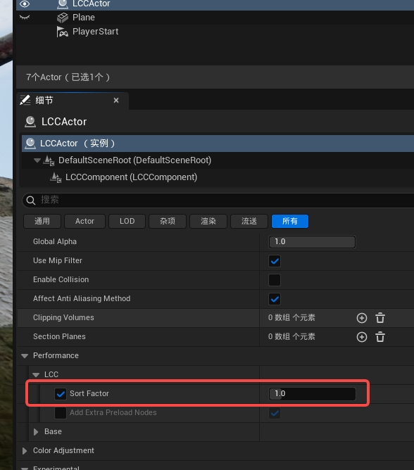
Setting Sort Factor to adjust the sorting frequency of the LCCActor
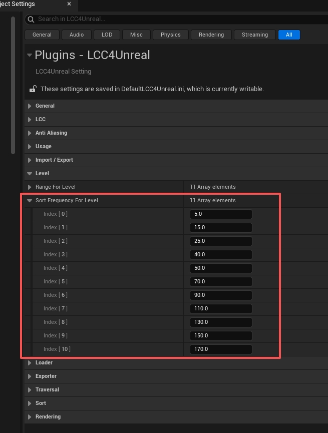
Configuring the Sort Frequency of each LOD Level
7.2 Extra Preload Nodes (LCC pipeline only)
For the range and default, see Performance Parameters: Add Extra Preload Nodes
Its purpose is to mitigate holes at the screen edge during fast rotation, at the price of more node work.
This option has two layers of state and is easy to get wrong:
- While the checkbox on the left is unticked, it falls back to the internal default, so the effective result is still enabled;
- To turn it off for real, tick the checkbox first, then set the value to disabled.
Turn it off only when the statistics show that node count and preloading really are a clear burden and the project can accept edge holes during fast turns. Restore it as soon as holes appear; do not paper over data that is not ready by adding threads.
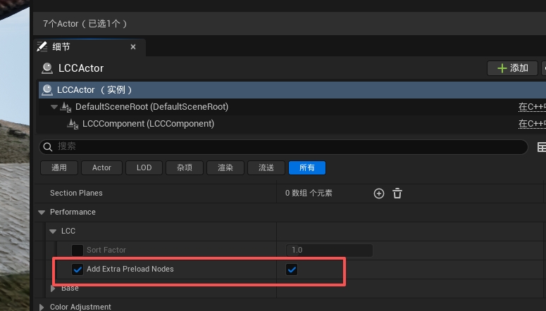
Configuring extra preload nodes to mitigate holes during fast turns
7.3 LCC2 GPU Memory Budget (LCC2 pipeline only)
For the range and default, see Performance Parameters: LCC2 GPU Memory Budget (MB)
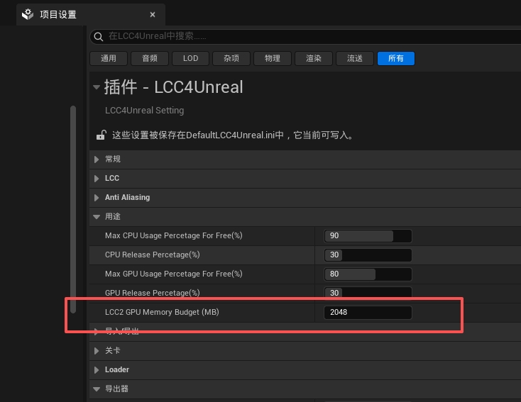
Setting the LCC2 GPU Memory Budget video memory budget
It counts only the position, color, and spherical harmonics data of a single LCC2 model. Raising the budget may help only in these cases:
- The GPU still has enough free video memory;
- Stutter mainly happens when moving into a new area or working with multiple viewports.
It does not reduce splat count, sorting work, or pixel coverage. Without eviction or fragmentation problems, raising the budget only increases resident video memory without improving the frame rate.
Tuning steps:
- Record the whole-machine video memory peak first, not just the LCC budget.
- Start from the default and increase in 1024 MB steps.
- Restart the engine after each change.
- Retest the most demanding viewpoints, all SceneCapture / nDisplay views, and long runs.
- Leave video memory for UE scene textures, Render Targets, Nanite, Lumen, VSM, sorting buffers, and the operating system.
Do not set it to 8192 MB without complete video memory monitoring.
The log also prints a breakdown of video memory usage, which can be used to check whether the budget is reasonable:
GPU footprint: %u slots (%s), %.2f MB total - gaussian %.2f, SH %.2f, sort %.2f (1 view), other %.2f MB
The sort item is the sorting buffer. The log is calculated for 1 view, so scale it by the view count for multiple viewports.
Step Eight: Loading, Threads, Memory
8.1 Do Not Add Threads First (LCC pipeline only)
For the range and default, see Performance Parameters: Thread Pool Settings
Adding threads may raise CPU concurrency, and it may also increase thread contention, context switching, momentary disk pressure, and upload peaks. Exporter threads have no direct relation to runtime rendering, so tuning them does not improve the frame rate.
Criteria: only when the statistics show the matching queue backing up while the CPU still has free cores, add 2~4 threads at a time and retest. When the CPU is already saturated, reduce the workload instead of adding more threads.
If the Create Thread item keeps showing time cost, the thread pool is expanding repeatedly, so adjust the pre-created count rather than the upper limit.
8.2 Splat Number For Discard Per Node (LCC pipeline only)
For the range and default, see Performance Parameters: Splat Number For Discard Per Node
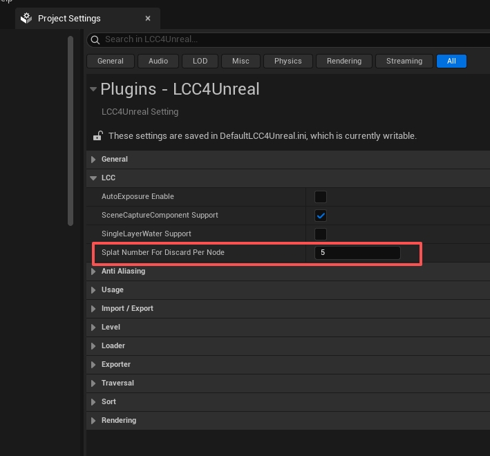
Setting the sparse splat discard threshold per node
Its intent is to ignore extremely sparse nodes: some datasets contain many nodes holding only one or two splats, and managing these nodes costs more than they contribute to the image.
Raising it may reduce the management cost of low-density nodes, and it may also remove isolated detail. Check at thin lines, tree branches, railings, and small distant objects rather than looking only at the overall frame rate. Reload the data after changing it, otherwise the result on screen is still the old one.
8.3 Memory and Video Memory Release Thresholds
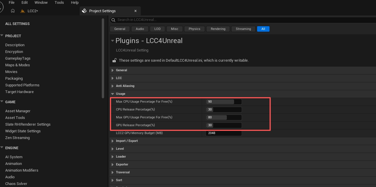
Configuring the CPU and GPU memory usage and release thresholds
For the range and default of the four thresholds, see Performance Parameters: Usage category
This is a release policy under memory pressure, not a regular frame rate knob:
- A threshold that is too low or a release percentage that is too large → may cause a "release, reload, release again" oscillation;
- A threshold that is too high → may delay release and increase system memory / video memory pressure;
- Adjust it only after long-running tests confirm memory pressure or repeated eviction.
Judge it by the relationship between CPU Occupy Percentage / GPU Occupy Percentage and the matching thresholds, and by whether Released CPU Node Num / Released GPU Node Num keeps growing. In the screenshot, video memory usage of 86% already exceeds the 80% threshold and the video memory release count reached 1943, which is a typical signal of video memory pressure.
Step Nine: Multiple Viewports, Collision, Water
9.1 Multiple Cameras and SceneCapture
Every additional view that actually takes part in rendering may add traversal, rendering, or sorting work; LCC2 also adds a sorting buffer per view.
Check item by item:
- Whether any SceneCapture is unused but still updating every frame;
- Whether the Render Target resolution is too high;
- Whether the update frequency really has to be every frame;
- Whether
ShowOnlyActorscontains only the needed content; - Whether the minimap can switch to
PointCloudor a lower resolution; - Whether nDisplay, split screen, or MRQ created extra views at the same time.
Use Camera Num(Render) in stat xgrids to confirm that the number of views actually rendering matches expectations; Camera Num is the number of cameras taking part in updates, and the two may differ. A value higher than expected means some views are rendering without your knowledge.
SceneCaptureComponent Support can be turned off when SceneCapture is not used at all; see Performance Parameters.
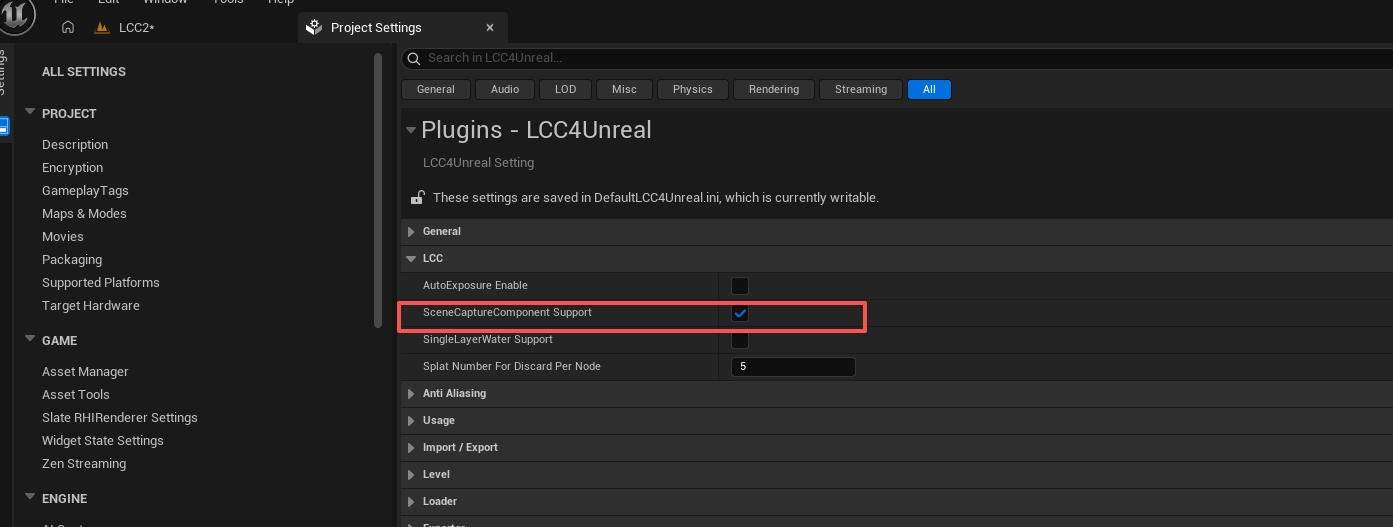
Configuring SceneCaptureComponent Support for multiple viewports
9.2 Traversal Mode
For the range and default, see Performance Parameters: Default Traversal Type
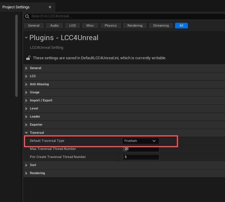
Selecting the Frustum or Circle default traversal mode
Circle suits curved screens, nDisplay, and 360 panoramas that need data in every surrounding direction; Frustum is the default baseline for a single viewport.
Do not switch an ordinary single-camera project to Circle just to "prevent missing chunks in any direction": it brings the entire circular range around the camera into traversal, while the frustum mode only processes the part that is visible. If the workflow requires Circle, tighten Max Distance, the point limit, and the multi-viewport resolution accordingly.
The LCC2 pipeline does not need this option adjusted; keep Frustum.
9.3 Collision and Navigation
For the feature description, see Collision and Navigation System Support. This section covers only the performance trade-offs.
With collision off, there is no collision distance to tune. Once enabled, collision reads, async physics baking, and NavMesh updates may add CPU cost, memory, and stutter. Note that such cost does not necessarily show up in FPS and needs the collision-related statistics to be inspected separately.
For the range and default of the collision distance, see Performance Parameters: Max Load Collision Distance(m)
- Turn collision off outright in presentation-only projects.
- When collision is needed, tick the checkbox to the left of the parameter and set
Max Load Collision Distance(m)to the actual interaction range.
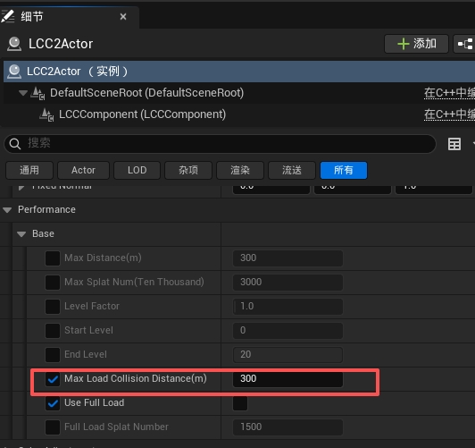
Setting the Max Load Collision Distance collision load distance
Dynamic collision range changes after adjusting the collision load distance
- Do not mechanically set the render distance and the collision distance to the same value. Visible in the distance does not mean physical collision is needed there.
- Reducing the collision distance directly limits the range available to player interaction and AI, so run a functional regression after changing it rather than looking only at the frame rate.
The strategy is the opposite when navigation is used: the collision distance should cover as much of the player-reachable area as possible so the collision of those areas is loaded in one pass. Collision is loaded dynamically in chunks, and swapping in a new collision chunk at runtime triggers a navigation data rebuild, causing noticeable stutter.
Supporting points:
- Have
NavMeshBoundsVolumecover the player activity range, and confirm the collision within that range is fully loaded - Prefer Static baking and avoid Dynamic baking, since the latter keeps rebuilding whenever collision changes
9.4 Single Layer Water (LCC2 pipeline only)
For the feature description and full configuration, see Single Layer Water Support. This section covers only the performance trade-offs.
SingleLayerWater Support is a global option in the project settings, but its implementation relies on the median depth of LCC2, so it does not take effect on Actors of the LCC pipeline.
- Keep it off when single layer water is not used;
- A restart is required after enabling it;
- The cost is that water pixels lose virtual shadow map shadow quality, which is a functional trade-off rather than a pure performance one;
- Enable it only when 3DGS is incorrectly occluded by a single layer water material.