Model Reconstruction
After model creation is complete, click "Start" to load the data. Once data loading is complete, the My Models list page opens. In the specific project within the model list, click "Start Reconstruction", then click "Confirm" in the prompt to begin automatic model generation.
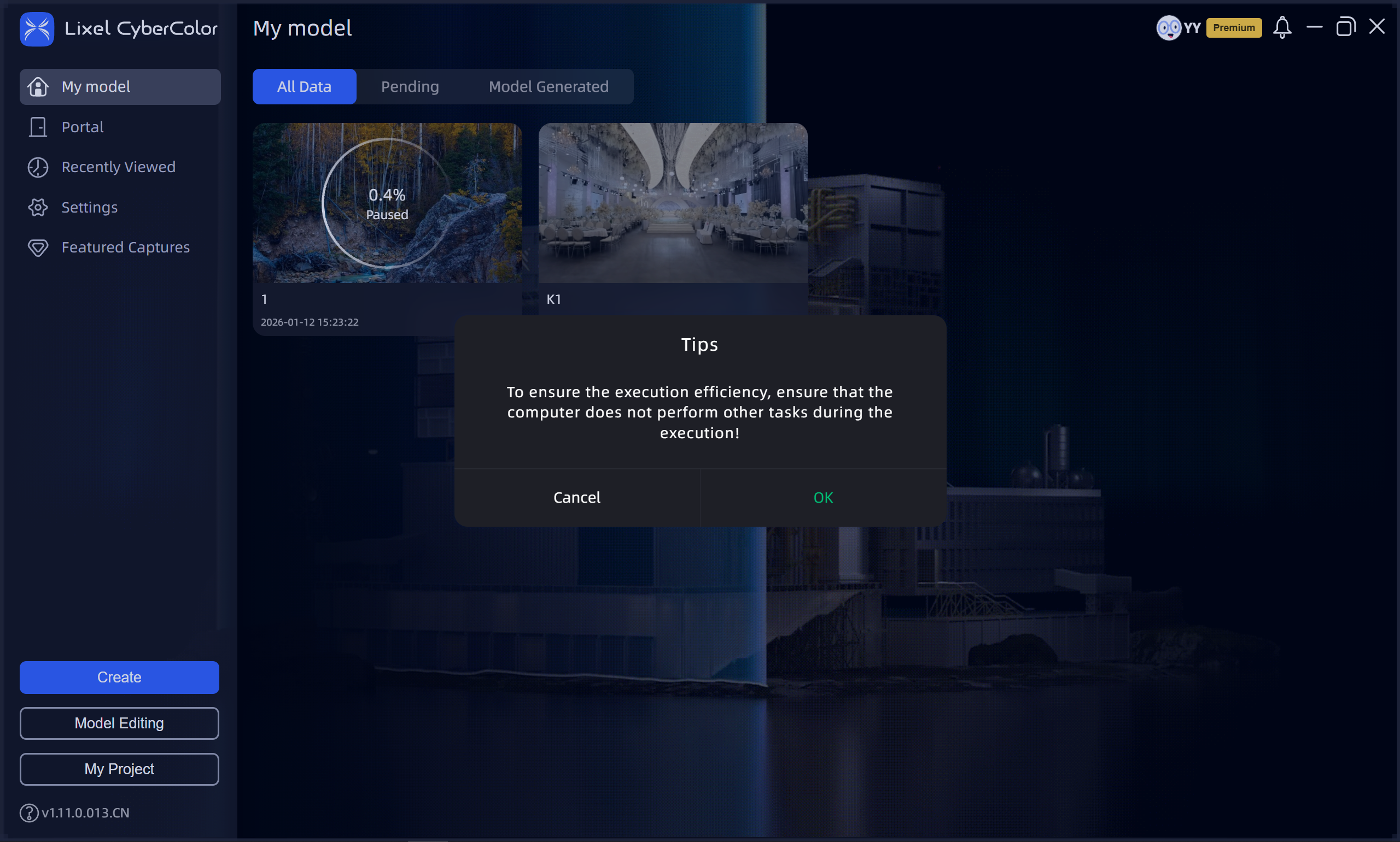
Start Reconstruction
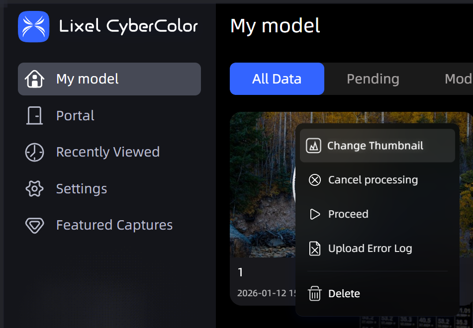
Reconstruction model card
Note:
- When running batch reconstruction tasks, ensure all data to be processed has been uploaded before queuing for reconstruction. During reconstruction, to avoid failure, it is recommended not to run other tasks that consume GPU memory on the computer.
- During reconstruction, do not close LCC Studio, otherwise the reconstruction task will be interrupted.
- When uploading capture data, ensure sufficient disk space in the LCC data save directory. Reserve at least twice the amount of disk space as the capture project data to prevent interruption or failure caused by insufficient space.
- If LCC Studio is closed during model generation, generation is interrupted. When LCC Studio is reopened, the model shows reconstruction failure and the previous reconstruction progress. Click the upper right corner of the model card and select "Continue Generation" or "Restart Generation" to re-enter the model generation queue.
Reconstruction Parameters
Reconstruction Quality
Different quality options (Fast, Standard, Slow) generate models with different signal-to-noise ratios. Slow reconstruction significantly increases VRAM consumption. Although this extends model generation time, it ultimately produces higher quality model results.
Maximum Gaussian Points
In single model reconstruction mode, the maximum Gaussian points directly limits the total point count of the final reconstruction result. Keep this within the VRAM capacity (typically no more than 25M). Setting it too high may cause insufficient VRAM or reduced reconstruction performance, affecting final model quality and stability.
In Map Fusion, Aerial-Ground Map Fusion, and Aerial Reconstruction modes, the maximum Gaussian points only applies to the reconstruction scale of individual blocks and does not limit the total Gaussian point count of the final complete model. LCC Studio automatically adjusts the reconstruction range of each block based on model size, so even setting the maximum Gaussian points above 25M will not significantly affect the overall reconstruction result.
Portability Optimization
Helps you generate LCC models that are compatible with most devices for loading. When optimization is enabled, LCC models are reduced in size with improved smoothness, adapting to most model requirements and especially improving mobile rendering quality. When optimization is disabled, more realistic lighting effects can be achieved, but may cause performance degradation or stuttering.
Debug Options
Debug options are a set of advanced configuration parameters for advanced users or developers, used to fine-tune the 3D reconstruction process, diagnose anomalies, or handle precision and compatibility requirements in specific model scenarios.
Exposure Optimization:
Specifically optimizes floating artifact issues in scenes with dramatic lighting changes (such as indoor-to-outdoor transitions), but may cause slight detail degradation in bright/dark areas. Enable this only when encountering such issues.
PPR (Point Cloud Participation Rate):
If sky adhesion occurs (e.g., at tree or building edges), try rebuilding with reduced PPR.
Note: Adhesion is usually caused by single-angle capture. Supplement with multiple angles and heights during capture for best results.
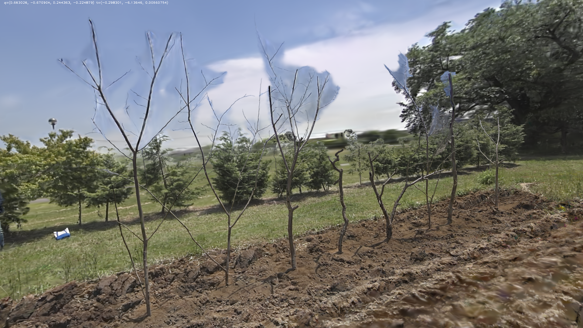
Before reduction (Normal)
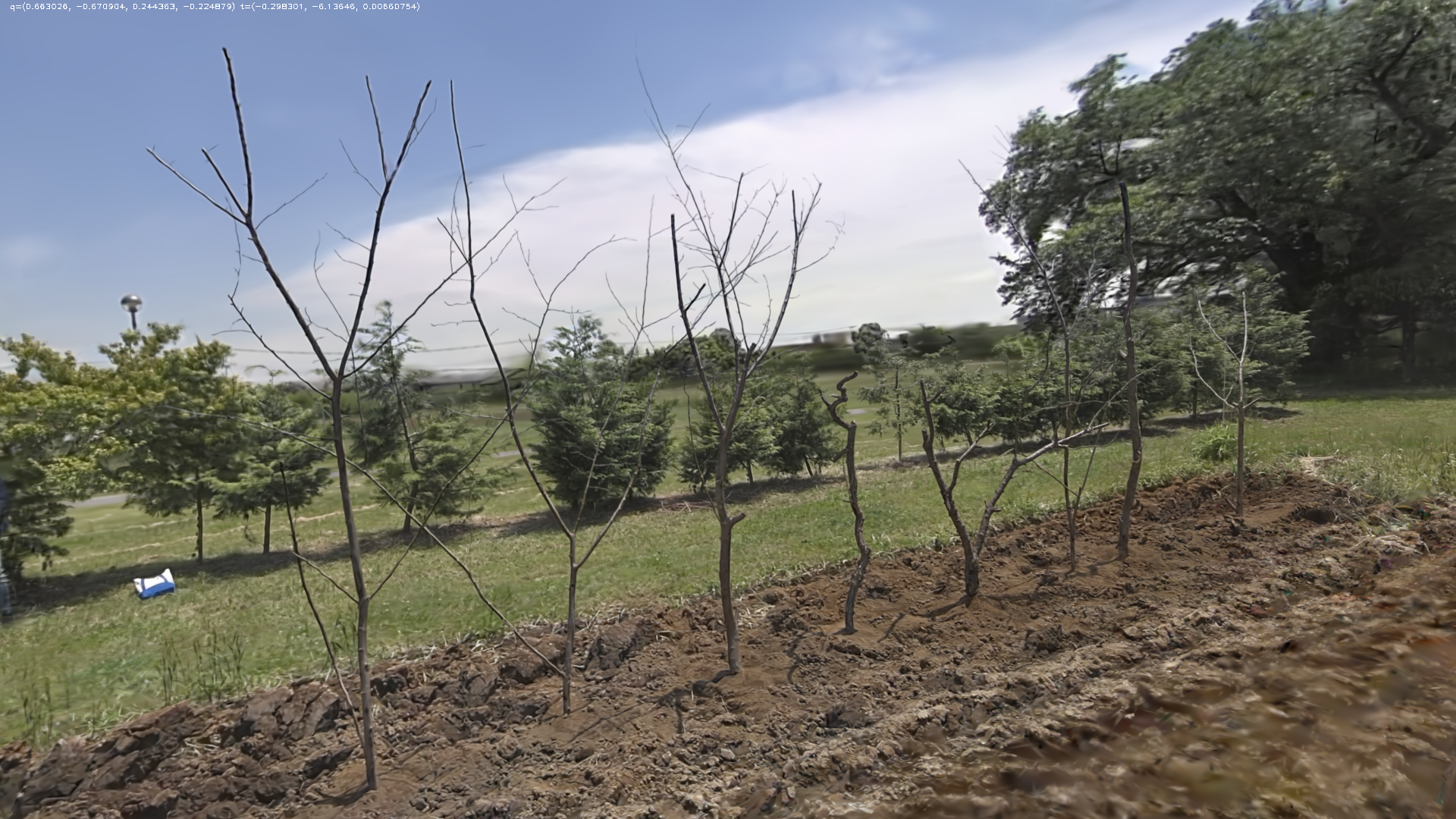
After reduction (Low)
RTK Data:
⚠️ Since v2.0.0, this option has been replaced by the "Coordinate System Conversion" feature. The [RTK Data] toggle is no longer available in Debug Options. See the Coordinate System Conversion section below.
v1.x version notes (click to expand)
Controls whether RTK data recorded during scanning is used in the reconstruction process:
- Auto: LCC Studio attempts to use RTK data first. If anomalies are detected, it automatically skips RTK data to ensure stable, reliable reconstruction.
- Disable: Completely ignores RTK data. The result will not contain absolute coordinate information and cannot be used for Map Fusion or aerial-ground alignment, but can avoid issues caused by anomalous RTK data.
SLAM Special Mode:
You can select a SLAM mode that matches your usage environment for better reconstruction results:
- Auto (Recommended): Intelligently matches the best reconstruction strategy. Prioritizes high-precision mode; if jitter or interference causing failure is detected, automatically switches to robust mode for retry, ensuring reconstruction success rate. Suitable for most scenarios.
- None: Pursues high modeling precision, suitable for stable devices and clear environments. Reconstruction may fail if jitter or interference occurs during capture.
- Robust Mode (Default): Suitable for most scenarios, balancing precision and stability with some interference resistance during capture.
- Narrow Scene: Optimized specifically for narrow environments such as tunnels, mine shafts, and long corridors. Using this in normal scenarios may cause failure.
Pre-Reconstruction Point Cloud Preview
After uploading capture data and before starting reconstruction, use the point cloud preview tool to view the capture trajectory and point cloud.
Steps: Upload capture data - Click Point Cloud Preview.
LCC Studio checks each indicator in turn. Adjust capture data based on the results before reconstruction to improve success rate and quality.
After the check completes, click View Point Cloud to open the preview tool and view the capture trajectory and rough scan point cloud.
The point cloud preview tool operates the same way as LCC Scene Editor.
Coordinate System Conversion
When your scan data contains RTK positioning information, you can set coordinate system conversion in the reconstruction parameter panel so the reconstruction output is delivered directly in the target coordinate system, making it easy to overlay with GIS/BIM data.
This feature replaces the legacy "RTK Data" debug option. The legacy version required manually judging RTK availability and selecting "Auto/Disable"; the new version hands this judgment to the system automatically — if RTK data is available, the system completes coordinate conversion automatically; if RTK data is unavailable or anomalous, the system skips coordinate conversion and outputs the model normally without affecting the reconstruction result. Simply select the target coordinate system.
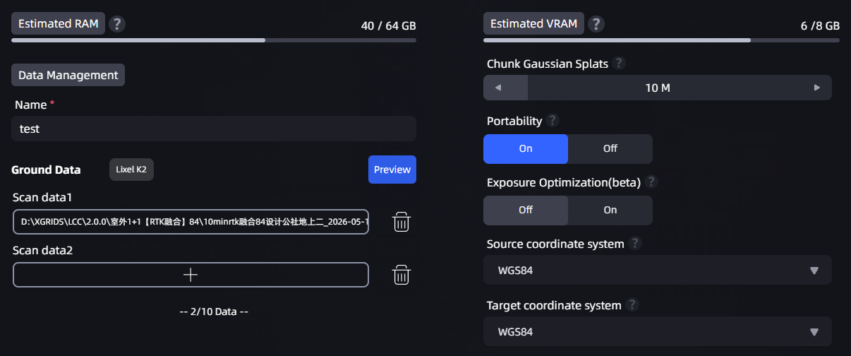
Location of the coordinate system conversion dropdown in the reconstruction parameter panel
How to Set
- In the reconstruction parameter panel, find the "Source Coordinate System" and "Target Coordinate System" dropdowns.
- The source coordinate system is identified automatically from your scan data (defaults to WGS84 when RTK is present).
- Select the coordinate system you need from the "Target Coordinate System" dropdown.
- Click Start Reconstruction. When reconstruction completes, the point cloud is automatically converted to the selected coordinate system.
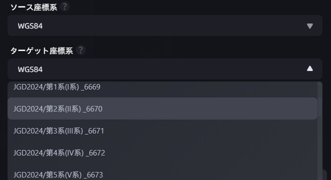
Target coordinate system dropdown expanded
Available Coordinate Systems
The available coordinate system options vary by your software language setting:
| Software Language | Available Target Coordinate Systems |
|---|---|
| Simplified Chinese | None · WGS84 · CGCS2000 |
| Japanese | None · WGS84 · Japan coordinate systems (19 zones) |
| English | None · WGS84 |
- Selecting "None" applies no coordinate conversion and outputs the local coordinate system (default behavior).
- Selecting another coordinate system requires scan data that contains RTK positioning information.
Error Handling Logic
| Scenario | System Behavior |
|---|---|
| RTK data is normal | Automatically completes coordinate conversion; model contains absolute coordinate information |
| RTK data is abnormal (signal loss/insufficient precision/false fix) | Automatically skips coordinate conversion; model is generated normally but without absolute coordinates |
| No RTK data (e.g., indoor capture) | Coordinate system option automatically shows "None" and cannot be changed; model is generated normally |
Note: If the scan data does not contain RTK information, the coordinate system option shows "None" and cannot be changed. When selecting a Japan coordinate system, you must further select the specific zone (1–19).
Layering Optimization
In the Advanced Tuning collapsible panel, a "Layering Optimization" toggle has been added, enabled by default. This feature applies only to scan data from Lixel P1 (Pcam) devices; for other devices the toggle is grayed out and unavailable.
How It Works
"Layering" refers to visual anomalies in the reconstructed model such as misalignment, ghosting, or structural fractures (e.g., a wall appearing as two layers, or the floor and ceiling being offset). These issues typically occur during large-range loop path capture due to accumulated positioning drift.
Layering Optimization corrects this accumulated drift through loop closure detection. When scanning a large loop path (such as circling a corridor, moving across multiple floors, or passing through the same area multiple times in a large scene), enabling this feature significantly reduces model misalignment and ghosting.
When to Enable (Default)
- Large-loop scenes (circling a long corridor, multiple floors, or passing through the same area multiple times in a large scene)
When to Disable
- Scenes with multiple areas of highly similar texture or layout (such as cubicles, repeated floors, symmetrical corridors, or chain stores)
Note: In scenes with similar textures, Layering Optimization may misidentify different locations as the same location, causing structural distortion in the model. If the reconstruction result looks abnormal, try disabling this toggle and rebuilding.