
Tools
This chapter covers point cloud post-processing tools, including registration, denoising, format conversion, sectioning, clipping, and data recording.
Manual Registration
Register different point clouds by selecting corresponding feature points.
- Select two point clouds in the data list.
- Click Registration.
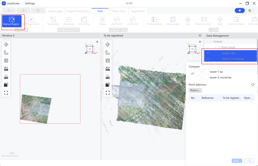
- (Optional) Click the arrow to swap the reference/target relationship between the two point clouds.
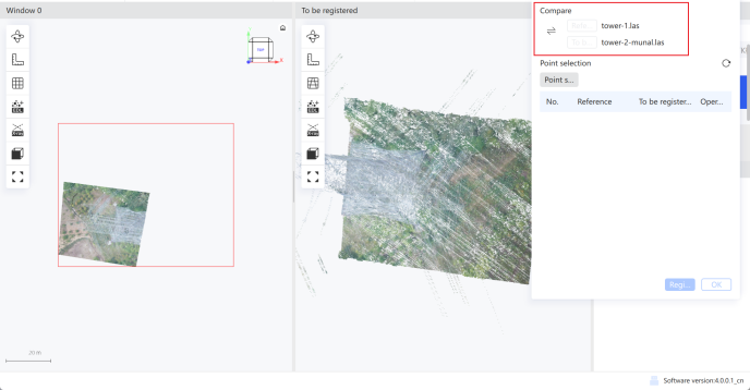
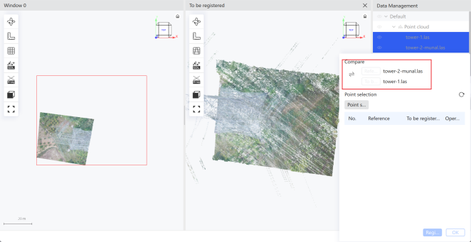
- Click + to add corresponding points, then select the matching points in both the reference and target windows. Select at least 3 corresponding connection points.
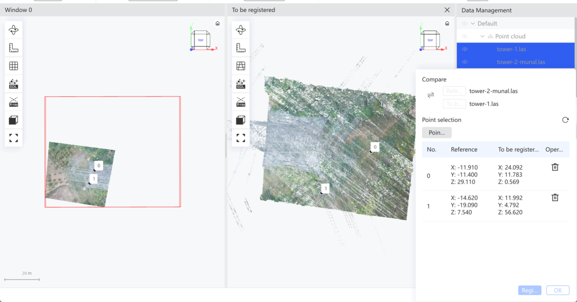
- Click Register. The software registers automatically and displays the RMSE on completion.
- (Optional) If unsatisfied, click Reset to reselect and register again.
- Click Confirm. A new registered point cloud is generated in the data list, and both point clouds are imported into a single window.
Note: Choose regular, well-defined terrain feature points. Avoid points that lie on the same plane or the same line, as this degrades registration quality.
ICP Registration
Improve registration accuracy when two point clouds are already approximately aligned.
- Select two point clouds in the data list.
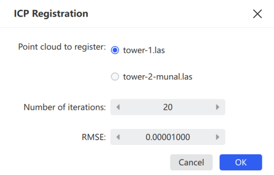
- Click ICP Registration.
- Set the parameters, then click Confirm. A new registered point cloud is generated in the data list.
| Parameter | Description |
|---|---|
| Maximum Iterations | Maximum iterations for the registration calculation. Default 20, range 1–100 |
| RMSE | Error threshold between the two point clouds after registration. Default 1e-9, range 1e-4 to 1e-10 |
| Voxel Radius | Processing resolution parameter |
Resampling
Resample point cloud data to reduce the point count.
- Set the sampling type and its parameters.
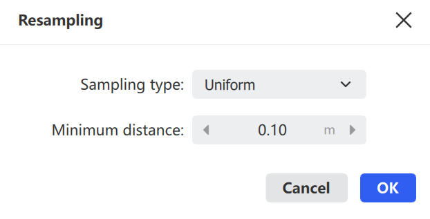
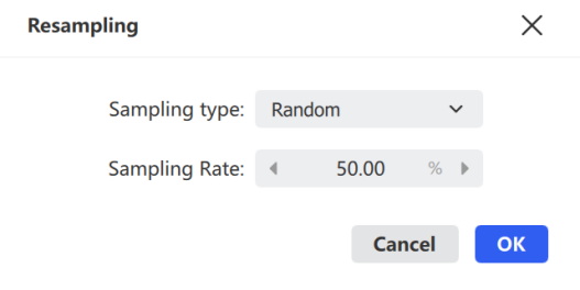

Resampling result in the data list
- Click Confirm to start resampling.
| Sampling Type | Description |
|---|---|
| Random | Samples randomly according to the sampling rate |
| Uniform | Samples according to the minimum point spacing |
Denoising
Filter noise points using neighborhood analysis.
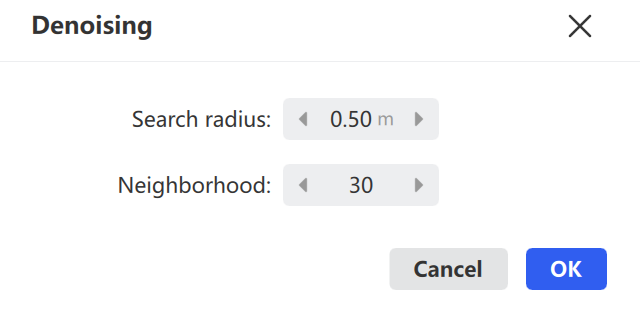
- Set the parameters:
- Neighborhood Points: The number of adjacent points analyzed per point. For sparse point clouds, increase this value.
- Standard Deviation Multiple: Noise detection sensitivity. A smaller value classifies more points as noise.
- Click Confirm to start denoising.
Note: The denoised point cloud is auto-imported. Export it via the File menu.
Smoothing
Smooth points on surfaces using a neighborhood radius algorithm to make some laser point cloud surfaces more even.
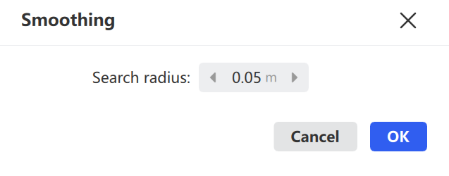
- Set the Neighborhood Radius. A larger radius produces a smoother result.
- Click Confirm to start smoothing.
Note: Use the default parameters for structured point cloud data. The smoothed point cloud is auto-imported.
Merge
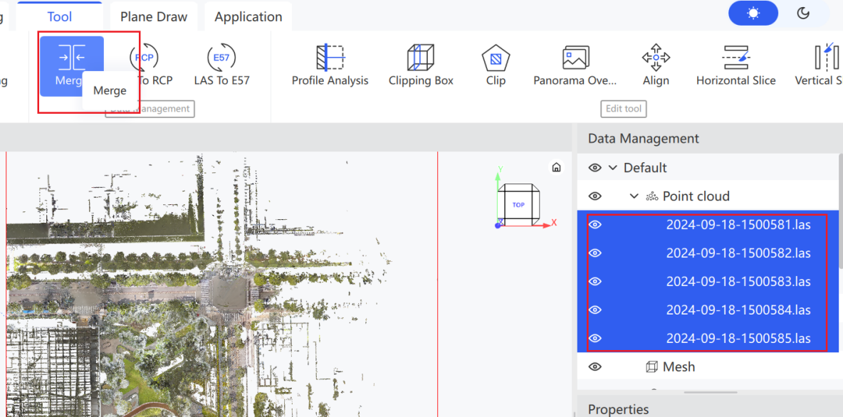
Combine multiple point clouds into one. Currently supports LAS versions 1.1–1.4 only.
- Select multiple point clouds in the data list, then click Merge (or right-click → Merge).
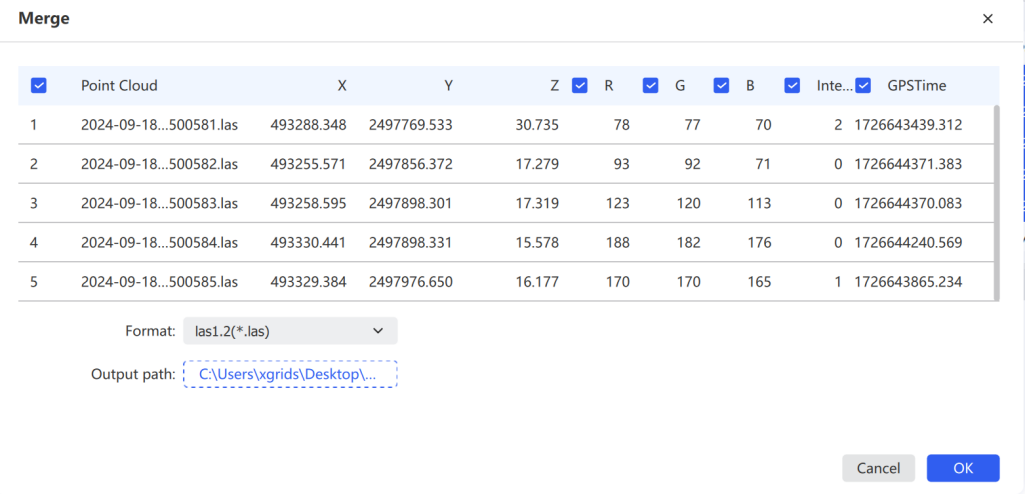
- Confirm the attributes to merge. By default all fields are merged. Uncheck specific fields to exclude them.
LAS to RCP
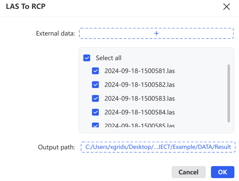
Convert up to 10 LAS files  to RCP format.
- Click the point cloud data in the data list, then click LAS to RCP under data conversion.
- (Optional) Click Import External Data to select additional LAS files that are not yet imported.
- Choose the output path and click Confirm to start conversion.
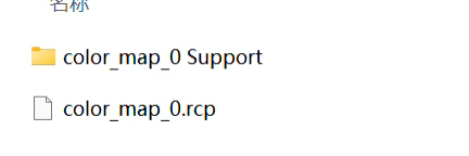
Note: The converted
.rcpdata consists of two parts — the.rcpdata index and its corresponding data folder. Copy both together when transferring to another path. The converted.rcpsupports AutoCAD and Recap 2020 and later.
LAS to E57
Convert .las point cloud data  to structured
 .e57.
- Click the point cloud data in the data list, then click LAS to e57 under data conversion.
- Select the pose file for the colorized point cloud (if absolute coordinates are present, select
pose_no_offset.csv), then set the panorama output interval. - Click Confirm to start conversion.
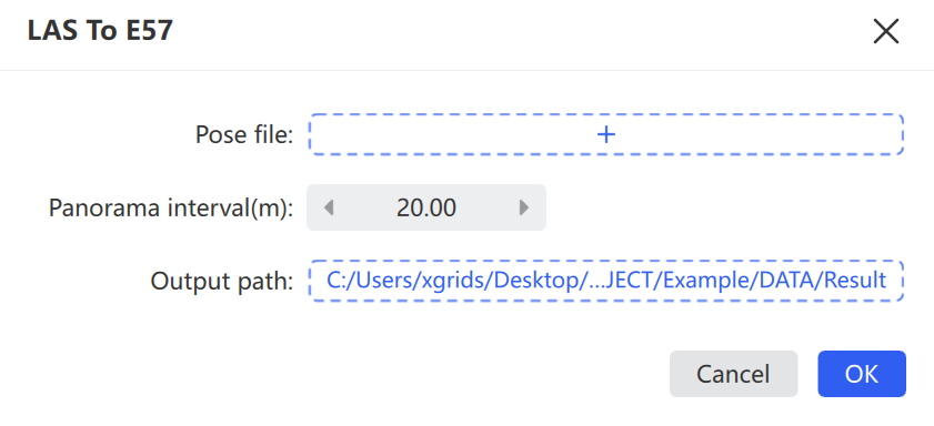
Note: Before converting to structured e57, import a colorized point cloud that has already output panoramic images, otherwise the conversion will fail.
Profile Analysis
Select any rectangular area in the point cloud to display that data in a separate window, with distance measurement supported.
- Select the point cloud data to view, then click Section.
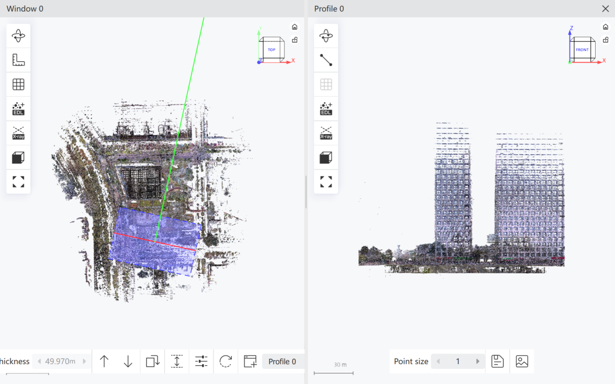
- In the main display window, click and drag to select the point cloud area to section. A toolbar at the bottom of the window provides adjustments. The sectioned data supports rotation mode, measurement toolbar, camera mode, EDL view, Xray view, view direction, and global view.


| Control | Description |
|---|---|
| Thickness | Enables the thickness parameter. A larger value widens the point cloud range included for display and processing |
| Move Up / Move Down | Moves the current section along the Y-axis |
| Rotate | Rotates the current section clockwise to adjust the cutting direction and angle |
| Extend | Extends the current section along the X-axis to view a larger range |
| Settings | Opens the section parameter settings panel |
| Reset | Restores the section parameters to their initial state |
| New Section | Creates a new section window |
| Point Size | Adjusts the display size of points in the section window |
| Save Point Cloud | Exports the point cloud within the current section range |
| Save Image | Saves the current section window as an image |
Clipping Box
Crop point cloud data using a clipping box.
- Select the point cloud data, then click Clipping Box.
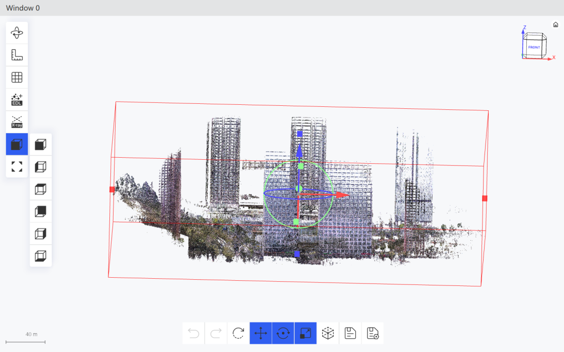
- Adjust the clipping box position.
- Click Close to exit.
Toolbar controls:
- Undo
 / Redo
  / Reset
  : Step back, step forward, or restore the initial state.
 - Translate
 / Rotate
  / Scale
  : Move the box, rotate it, or move individual planes.
 - Show Info Panel
 : Opens the panel for precise box dimensions, translation, and rotation values.
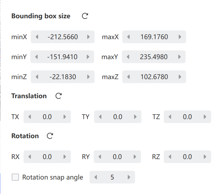
- Save
 : Displays the cropped result as a new point cloud. Save Settings
  : Configures the save content and location.
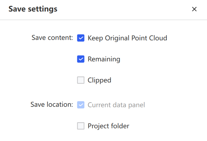
Clipping
Crop a portion of the point cloud. Click the data to clip, then click Clipping  .
.
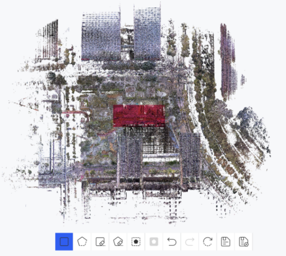
Rectangle Select  : Select a rectangular area in the point cloud. Left-click to set rectangle vertices, double-click to complete.
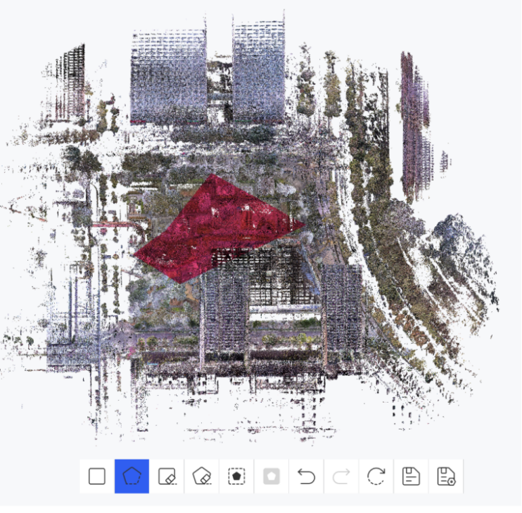
Polygon Select  : Select a polygonal area. Left-click to set vertices, right-click to cancel the last vertex, double-click to complete.
- Rectangle Delete
 / Polygon Delete
  : Cancel a selected area through a rectangular or polygonal region.
 - Crop Inside
 : Keep the selected area and delete the rest. Crop Outside
  : Keep the unselected area and delete the selection.
 - Undo / Redo / Reset / Save: Same as Clipping Box.
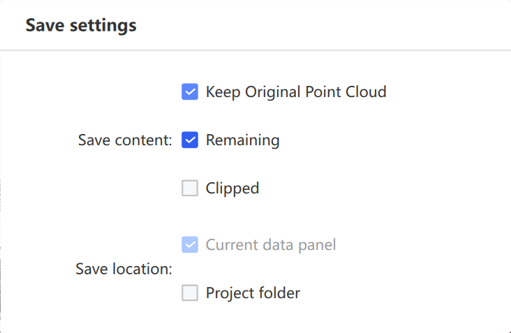
- Save Settings: Configure the save content (keep original / remaining portion / cropped portion) and location (current data list / project path).
Panorama Overlay
Overlay a panorama-colored point cloud with its panoramic imagery for browsing and measurement.
- Select the point cloud data.
- Click Panorama Overlay.
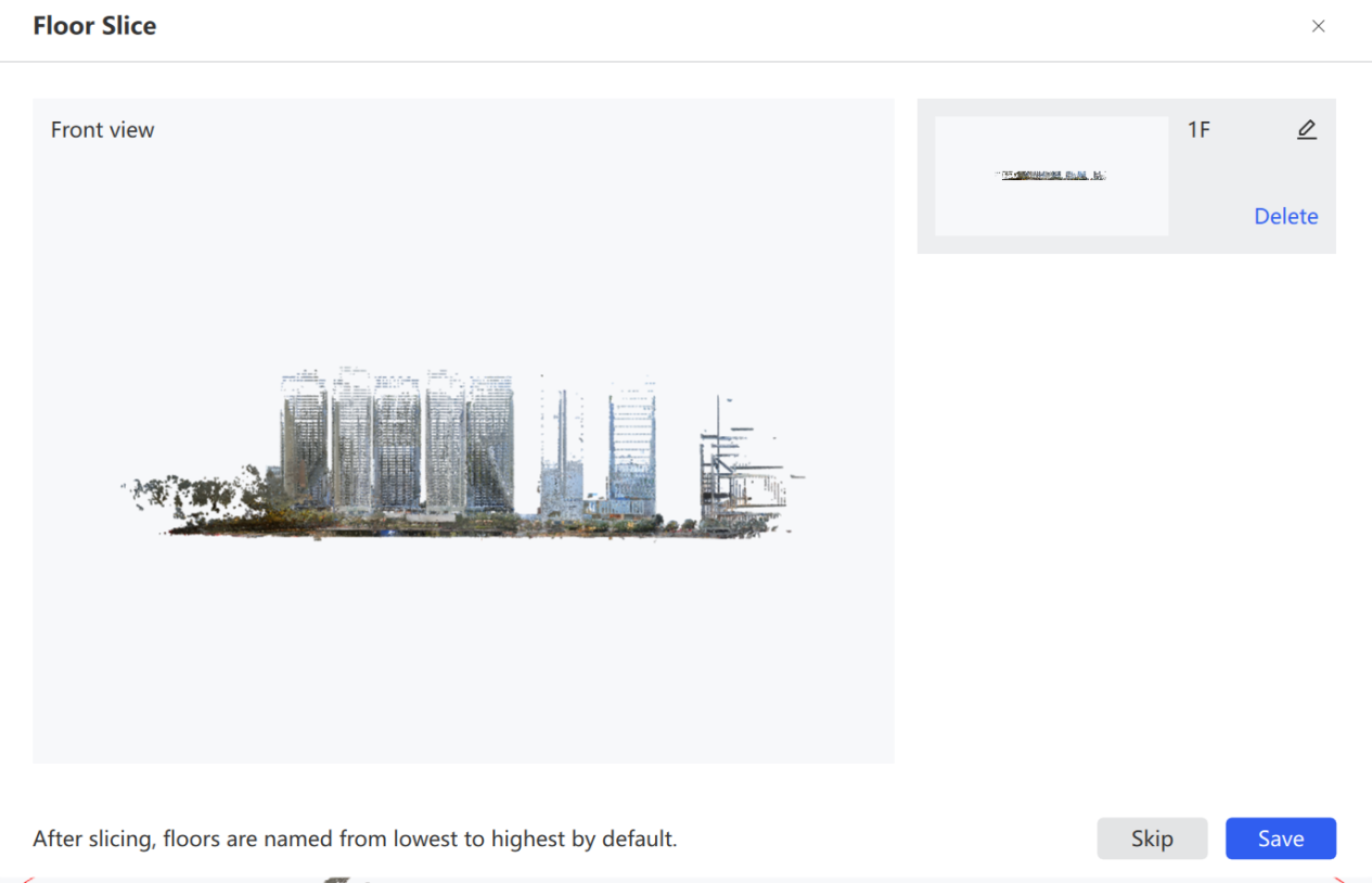
- (Optional) Choose whether to perform floor slicing.
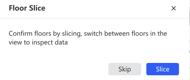
Perform floor slicing: left-click to select the start position, left-click again to confirm the end position. Slice results auto-save and display on the right. Click Save after slicing all floors to enter the overlay. Click Cancel to skip slicing.
- Enter the panorama overlay view. All floors and panoramic images display by default. Use the toolbar to overlay the point cloud or split the screen.

- Click a trajectory point in the view or minimap to switch positions. Use the minimap dropdown to select different floor data.
Toolbar controls:
- Point Cloud
 / Panorama Image
  : Toggle the point cloud or panoramic photo display.
 - Fit Trajectory to Ground
 : Automatically subtracts 1.5m of height to fit the ground. Original Trajectory Position
  : Default 0m.
 - Split-screen
 : Point cloud on the left, panorama on the right. Lock View Direction
  : Sync rotation across both windows.
 - Previous Frame
 / Play
  / Next Frame
  : Switch trajectory points or auto-play frame by frame.
Align
Adjust the posture of point cloud data. After selecting a coordinate axis, rotate the point cloud so it aligns with the required direction.
- Select the point cloud data to orient, then click the Orientation button on the menu bar.
- (Optional) Perform vertical orientation: in the front or left view, left-click to select the center point (right-click to cancel), then click again after confirming the axis direction.
- (Optional) Fine-tune the selected axis in the orientation adjustment floating window on the left.
- Click Apply to orient the point cloud.
- (Optional) Perform horizontal orientation: repeat the steps above in the top view.
- Click Save to save the oriented point cloud as a new point cloud.
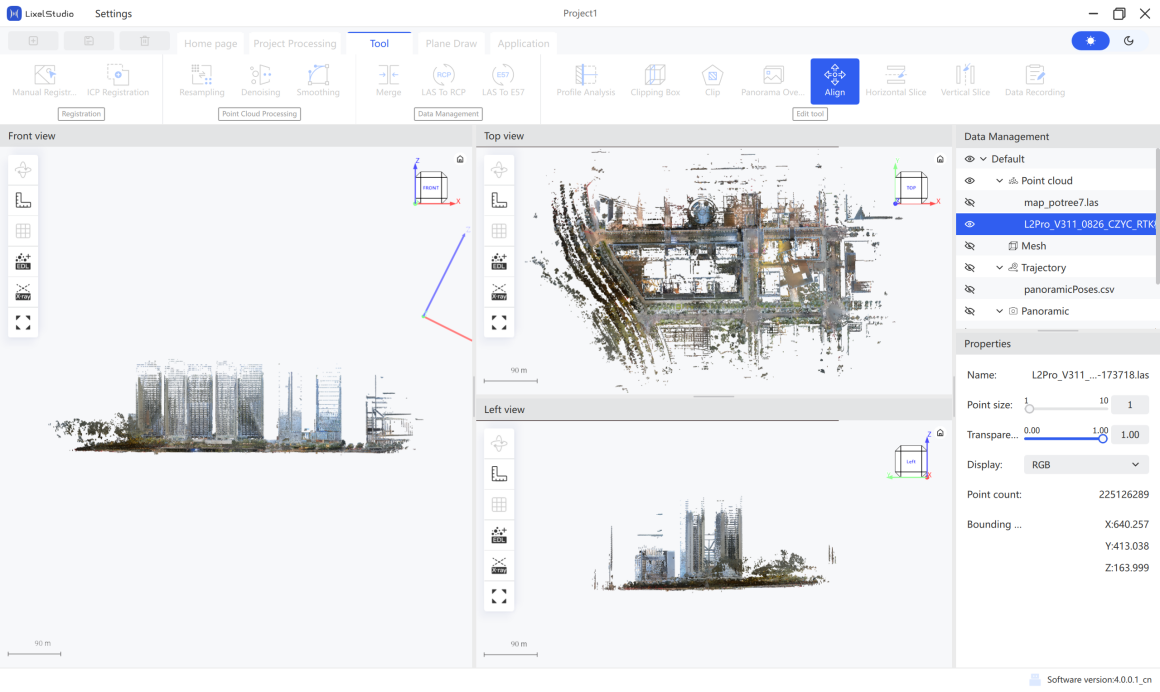
Note: Point cloud orientation changes the point cloud coordinates.
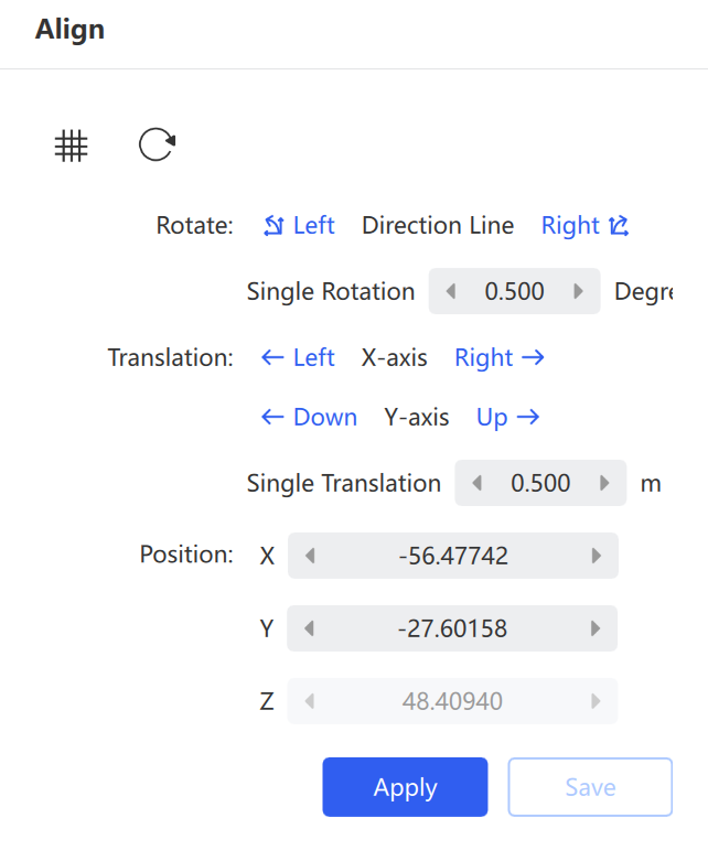
- Grid: Shows or hides the orientation auxiliary grid. Reset: Restores the point cloud to its initial state.
- Rotate: Adjusts the angle of the current orientation direction line. Click Left or Right to fine-tune by the specified angle.
- Translate: Moves the point cloud along the X and Y axes. The distance per move is controlled by the Single Translation parameter.
- Position X / Y / Z: Precisely sets the coordinate position of the point cloud after orientation.
Horizontal Slice
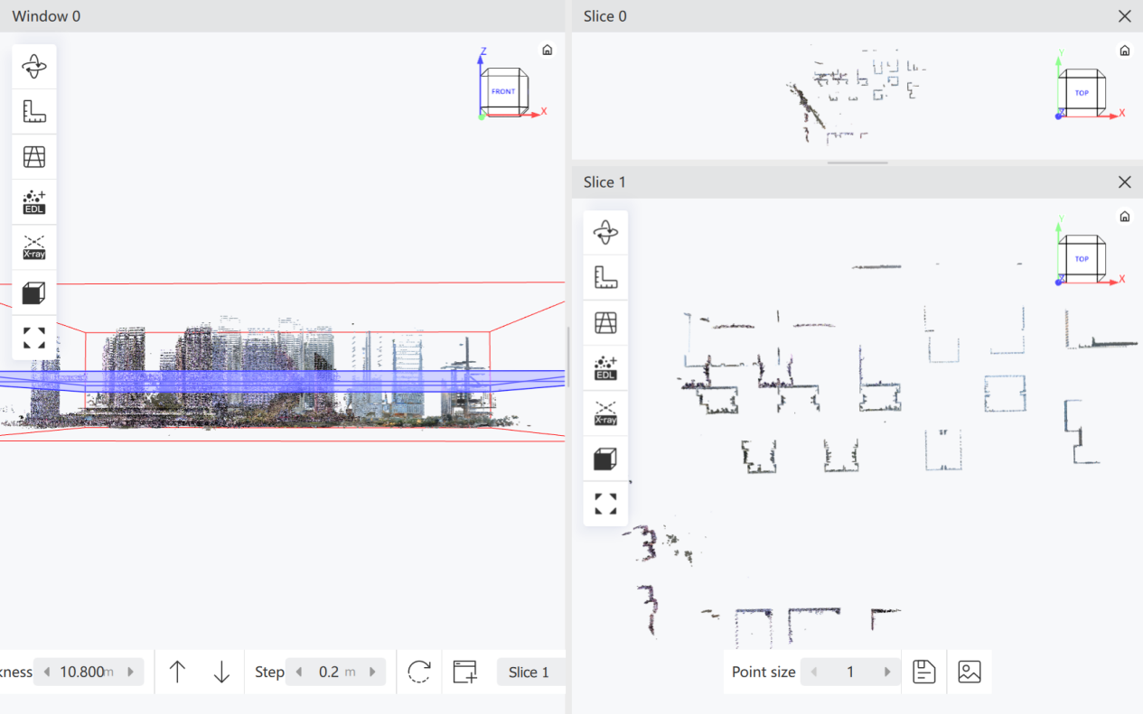
Section and display point cloud data along the horizontal direction. The system generates the slice based on the horizontal plane where the selected point is located.
- Select the point cloud data to slice, then click Horizontal Slice.
- In the main window, left-click to select a point. The system generates the slice based on the horizontal plane of that point.
- After the slice is generated, adjust the thickness using the Thickness parameter (
Shift + mouse wheelis also supported). - Click Move Up or Move Down to move the slice by the set step (
Ctrl + mouse wheelis also supported). - To browse continuously, set the Step Length and use the Move Up / Move Down buttons.
- Click Reset to restore the initial state; click New Slice to create a new slice; use the dropdown to switch the active slice.
- Click Save Point Cloud to export the slice, or Save Image to save the slice view.
Vertical Slice
Section and display point cloud data along the vertical direction. Specify a start point in the main window, then move the mouse to dynamically adjust the slice direction. After confirming the direction, click again to generate the vertical slice.
- Select the point cloud data to slice, then click Vertical Slice.
- In the main window, left-click to select a point. As you move the mouse, the slice rotates in real time following the mouse direction.
- After confirming the vertical slice direction, left-click again to generate the slice result and select the current section plane.
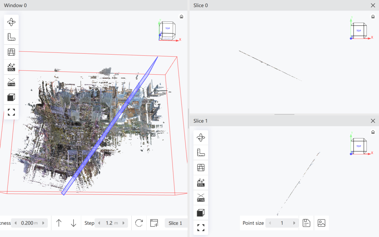
Other operations and parameters are the same as Horizontal Slice.
Data Recording
Perform measurements and annotations in the point cloud, capture screenshots of the current window, and export a report.
- Select the point cloud, then click Data Recording. A draggable floating window appears on the right.
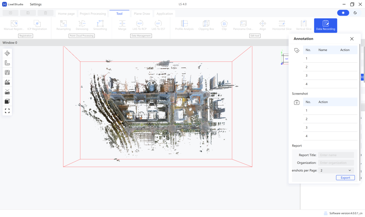
- Click the annotation button
 to enter annotation mode. Left-click in the point cloud window, enter text in the input box, and press
 Enterto confirm. English letters and numbers are supported. - (Optional) Click
 to show/hide annotations, or
  to delete an annotation.
 - After measuring the point cloud, click the screenshot button
 to capture the current window.
 - (Optional) Click
 to open the screenshot folder.
 - Enter the report name and organization name (company), and set the number of screenshots per page.
- Click Export to generate the report.
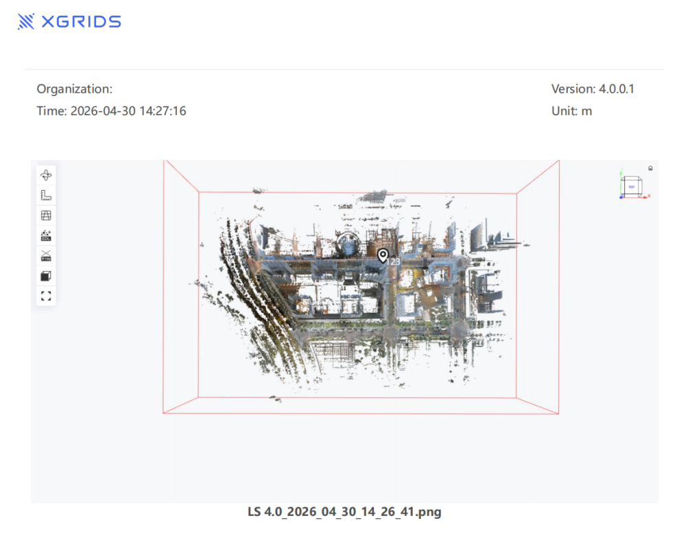
The export includes a screenshot folder (all screenshots), Annotation.csv (annotation coordinates), and the report file.