
Applications
This chapter covers industry applications, including volume calculation, volume comparison, enclosed volume calculation, and mesh generation.
Volume Calculation
Measure and calculate stockpile volumes from point cloud data.
- Select the point cloud.
- Click Volume Calculation
 .
.
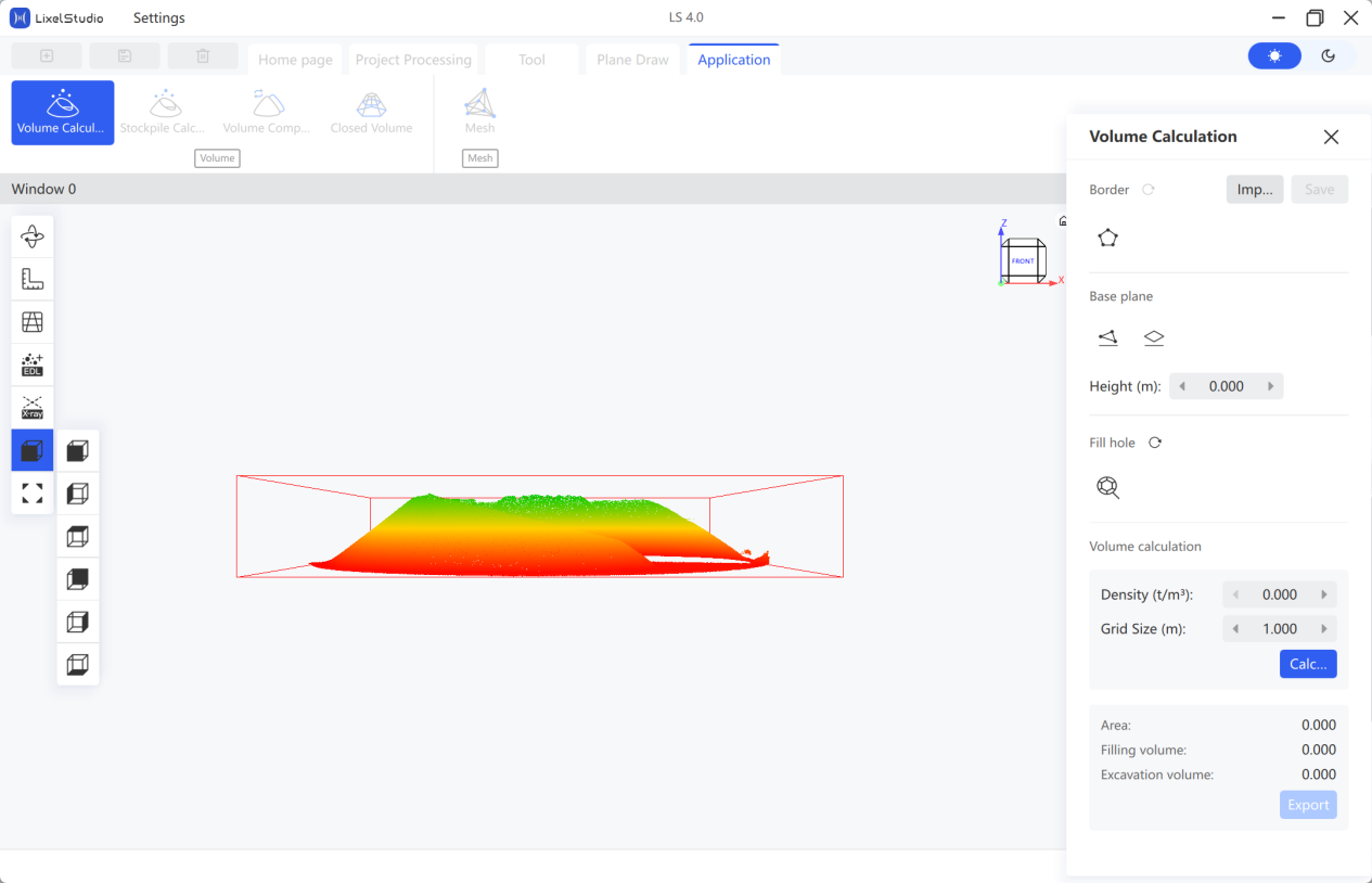
- Draw Border: Click Draw Border
 , left-click boundary points in the point cloud, and right-click to end. The stockpile range is auto-selected. Click the save button to save the border.
 - Select Base Plane:
- Method 1 — Three-Point Plane: Click the point selection button below the base plane, then click three points around the heap to draw the base plane.
- Method 2 — Horizontal Plane: Enter the base plane height in the popup. The base plane is auto-generated in the model.
- Fill Holes: Click Fill Holes
 , left-click to select points, and right-click to end. Click the reset button to reset the filling result if needed.
 - Set Mesh Parameters: Set the Mesh Density (the size of the point cloud mesh grid). Generally use the default parameters.
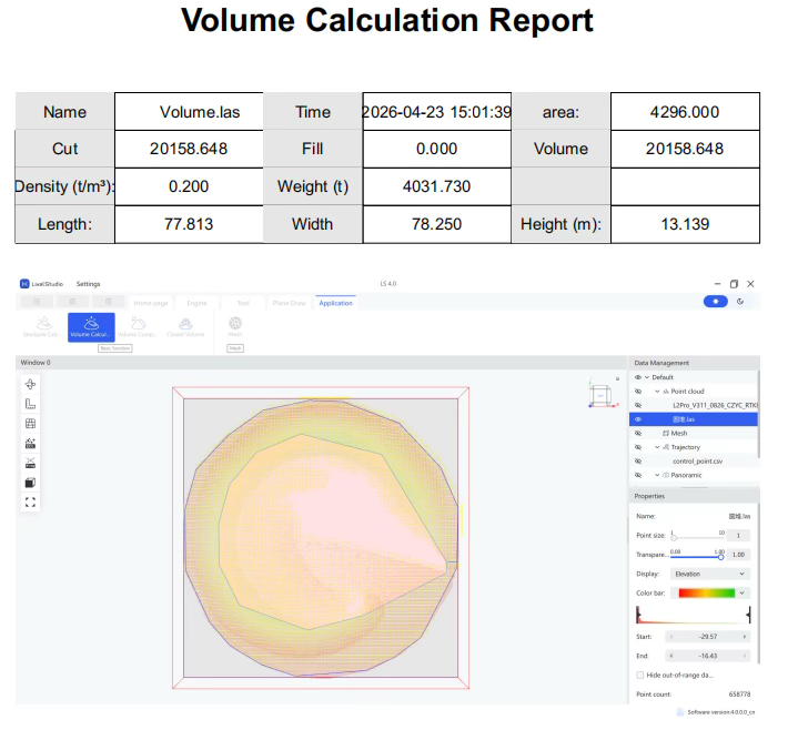
- Calculate: Click Calculate and view the results (filling volume, excavation volume).
- Export Report: Click Export Report, then select the save path and filename.
Volume Comparison
Compare two periods of stockpile data.
Note: The two periods of point cloud must maintain a consistent base plane. Registration is recommended.
- Select the point clouds.
- Click Volume Comparison
 .
.
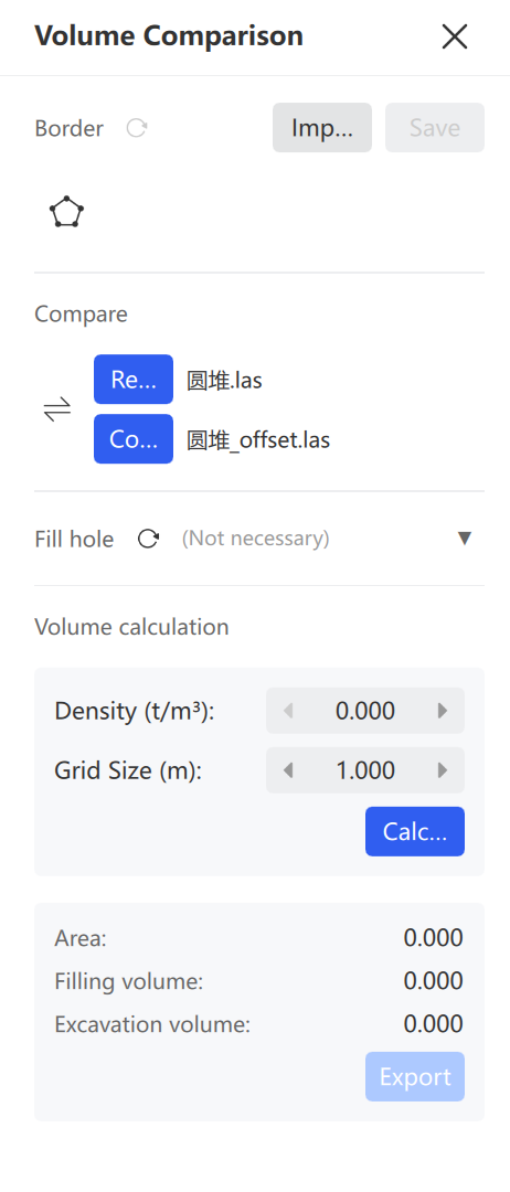
- Draw Border: Click Draw Border , left-click the boundary, and right-click to end. Click the save button to save the border.
- Confirm Base and Change: Identify which dataset is the base and which is the change. Click Switch
 to adjust if needed.
 - Fill Holes (Optional): Click the point cloud requiring hole filling and perform the operation.
- Set Mesh Parameters: Set the Mesh Density. Generally use the default parameters.
- Calculate: Click Calculate and view the comparison results.
- Export Report: Click Export Report, then select the save path and filename.
Enclosed Volume Calculation
Calculate the volumes of enclosed areas such as mine tunnels and cabins.
Note: Denoise and downsample the point cloud first so that the data contains only the calculation area.
- Select the point cloud.
- Click Enclosed Volume
 .
.
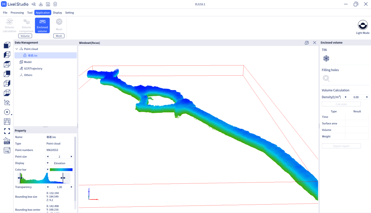
- Create Mesh: Click Mesh
 and wait for the TIN (Triangulated Irregular Network) to be built.
 - Fill Holes: Click Fill Holes
 . The software auto-fills mesh holes to obtain a complete enclosed model.
 - Modify Density (Optional): Adjust if weight calculation is not needed.
- Calculate: Click Calculate, select the
XXX_tinflXXXX.plyfile, and view the volume and surface area data. - Export Report: Click Export Report, then select the save path and filename.
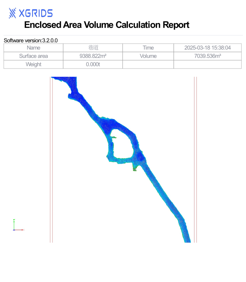
- Exit: Click Enclosed Volume in the menu to exit.
Mesh
One-click textured 3D mesh generation from L1/L2 laser point clouds with external panoramic camera data, and from K1/K2/L2 Pro point clouds with onboard panoramic camera data.
- Click Mesh.
- Input the scanned result data folder (after panoramic coloring).
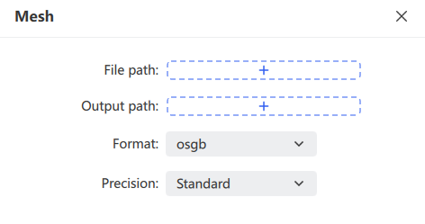
- Choose the export path and format (
.objor.osgb). - The software generates the textured 3D model.
Note: This version supports K1, K2, and L2 Pro result data with onboard colorization and panoramic photo output. It only processes post-processed
.lasresults under 50 GB.
Remote Transfer
Stream a handheld device's working data to LixelStudio in real time over a mobile network. Use it to remotely monitor operators and devices, start or stop scanning remotely and generate data in real time, and store the device's real-time discrete data as structured data for post-processing and other operations.
Note: Remote Transfer only supports K1 and L2 Pro devices with firmware 3.0 or later.
Steps:
- Click Remote Transfer
 in the menu bar to open the feature.
 - Choose a connection method.
- Click the target device to enter the live view.
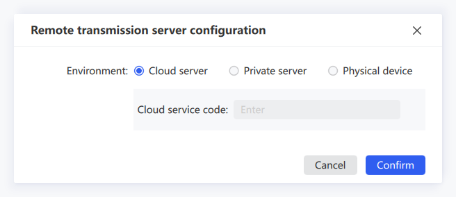
Remote Transfer offers three connection methods: Cloud Service Code, Private Server, and Physical Device.
Cloud Service Code
A cloud service provided by XGRIDS. Register and apply for a service code before use. Users sharing the same service code can see all cloud-connected devices under that code. Using the cloud service requires no self-hosted server; it handles data transfer, storage, and forwarding. Obtain the service code in advance by contacting your sales representative.
- Configure the mobile App: set the network transfer type to Cloud Service Code and enter the service code. For details, see the K1 and L2 Pro user manuals.
- After configuring the App, select Cloud Service Code in LixelStudio, enter the same service code as in the App, and click Confirm. The corresponding device is then displayed.
- Click the device. Once it starts recording, you can view it in real time.
Private Server
Use the remote transfer service through a private server address and access key. Contact technical support for private server deployment and access key generation.
Physical Device
Connect directly to the device via USB or WiFi.
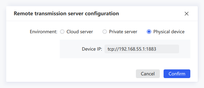
- For a USB connection, the IP address is usually
tcp://192.168.55.1:1883. For a WiFi connection, the computer must first connect to the phone hotspot (the same hotspot the device connects to). - Click Bridge Mode in the App to view the current IP address, then enter that IP on the computer. Once configured correctly, you enter the live view.
Live View Controls
| Icon | Control | Description |
|---|---|---|
 | Start Scanning | Remotely starts scanning on the device |
| Stop Scanning | Remotely stops scanning on the device | |
 | Reconnect | Reconnects after the network is interrupted |
 | Property Settings | Sets the point size, rendering mode (elevation, intensity, time, single color), and opacity of the real-time rendered point cloud |
 | Browse Mode | Switches between free browsing and trajectory-following browsing |
 | Pause/Resume Transfer | Pauses or resumes point cloud transfer. Click to pause; click again to resume |
 | Save | Saves the point cloud transferred in real time |
 | Close | Exits Remote Transfer |
Note: Point clouds during a pause are not saved in LixelStudio.